Just a quick update this time. The body has started to move, but I’m taking it slowly. So far it shifts about 3 mm then stops. I think the foam strips between the body and chassis are working like very stubborn glue. Oh that and the expanding foam which I prefer not to talk about – I thought it would be a good idea for the longevity of the chassis side rails to use expanding foam to fill the cavity. Its done a good job to exclude moisture but is hard work to remove. 3 hours per side so far and still more to do!
Honestly I’m not complaining its better than DIY and gardening…
It’s been far too long since my last update. Various home DIY projects have kept me away from the car for months. However I’m now able to spend some time to get back on-track.
I’ve been putting some work into developing my techniques for the eventual carbon fibre parts, but that’s a post for another day. No, what I’m doing now is preparing the car for a complete strip-down to the bare chassis.
Body-off progress
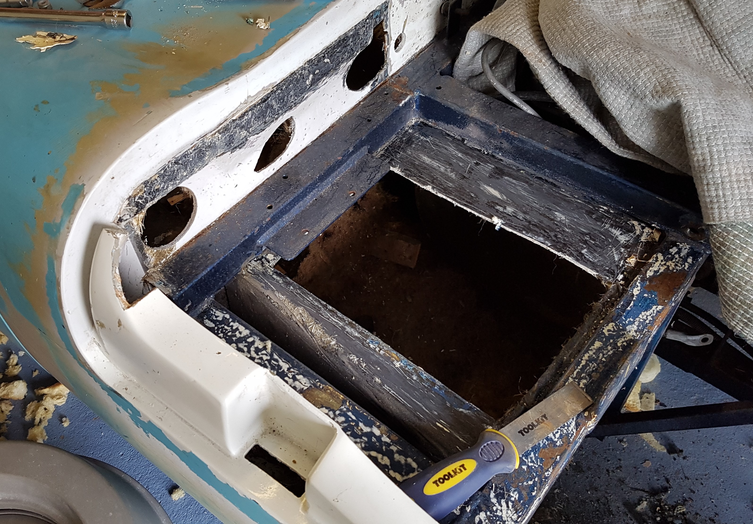
Progress is slow and deliberate. It involves finding and removing all of the self-tapping screws that attach the body as well as any other fittings that are attached to the chassis through the internal body tub GRP. One of the more alarming aspects of this process is to see just how rusty the lower chassis rails are. That’s a surprise as the car has never been on the road. It was just stored in a damp garage for 14 years or so.
Many of the screws were rusted in place and would not move whatever I tried. So I got myself an excellent DeWalt impact driver which has already paid for itself on numerous jobs. All but one screw came out in a matter of seconds. The impact driver is also compact enough that I could remove all six screws on the parcel shelf under the rear screen without a problem. I’m so pleased that I could avoid removing the screen or cutting the GRP around the screw.
The big clean-up
I love working on the Marcos most of the time, but the current task is pure drudgery. Very messy too… I’ll explain – When I originally built the Mantula, I used the supplied sound deadening felt. I was finding it difficult to make it stick on reliably. So, following the advice of an experienced car upholsterer I stuck it on with some sort of black tar-like glue. It did a great job of keeping the felt in place, but all these years later how do I get rid of it? It seems to soften with a suitable solvent, but I don’t want to damage the GRP, the best I have found so far is paint brush cleaner. But it just takes forever to clean up the black gloopy mess. The smell is nasty too.
However it will eventually all be gone so I will be able to work inside the car. Unfortunately this is still going to be a destructive process as I remove all of the ‘permanent’ modifications that I made during the original build.
Demodifying
I have to admit that the build quality of my Mantula was deeply disappointing. I’m sure the body panel alignment on my car is worse than any other. Back in that first summer of ownership when the reality of Marcos ownership dawned on me I was close to despair. Nothing fitted properly and many parts were just unusable. The plywood frame that supported the dash board was lose where the grp matting had missed the plywood completely!
Worse than any of that was the state of the GRP layup. In several places there was no glass matting, just gelcoat and resin! As you can expect these areas didn’t survive very long. So I had to repair them in the best way I could. Unfortunately my repairs were not as good as I expected, so I will have to rework them. The worst areas were the drivers side scuttle gutter and the centre of the front spoiler.
Scuttle gutter missing
In the picture above you can see where a large section of the gutter is missing. Doing a proper invisible repair won’t be easy.
Oh well, back to cleaning off the glue, more soon…
Wow, it’s really been three months since I last worked on the Marcos! Sometimes other things get in the way. So it’s been months of DIY and decorating that has left the Mantula untouched. Hopefully I can get back to it in December. In the meantime here’s a picture…
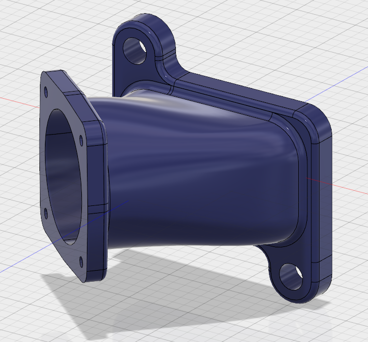
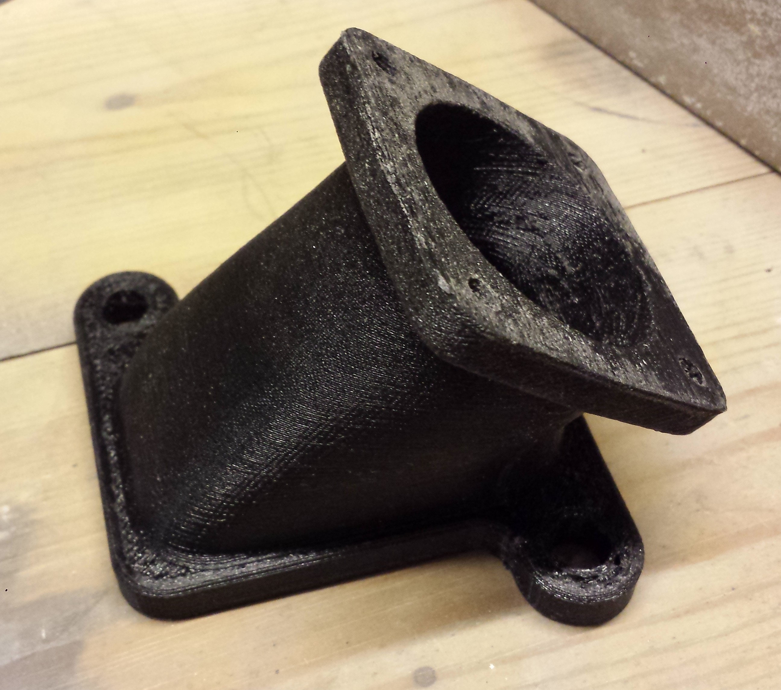
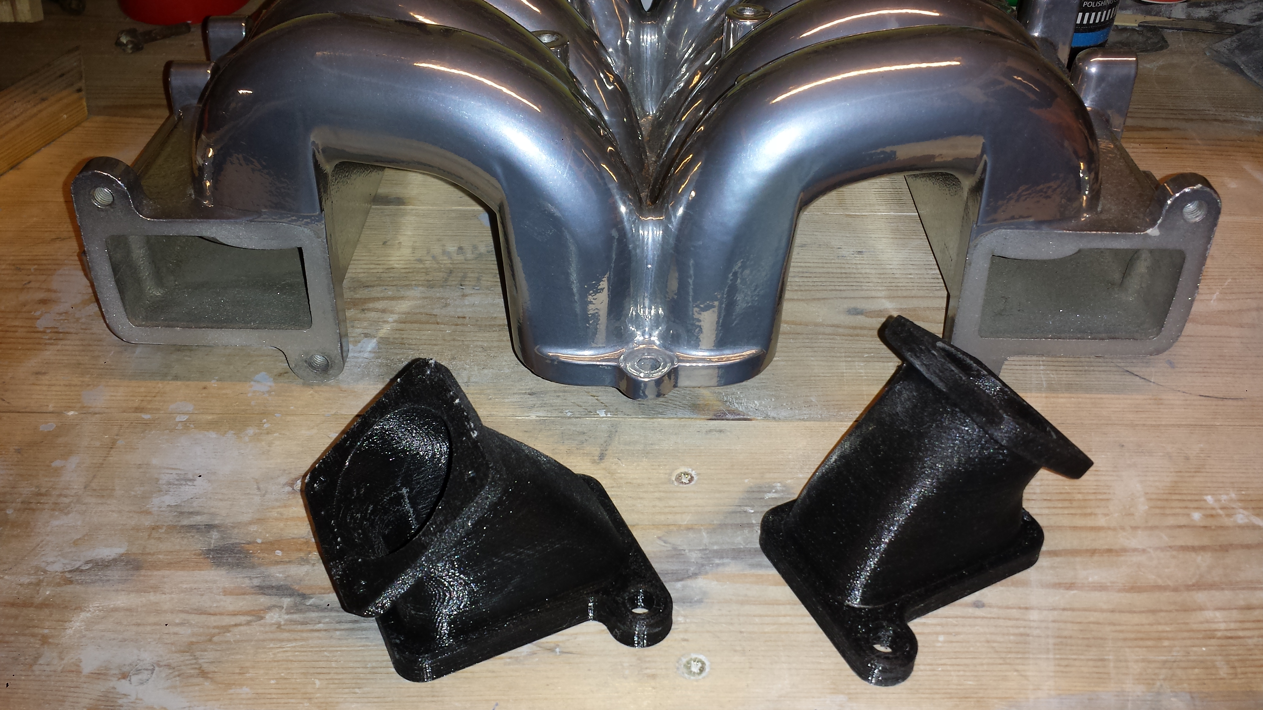
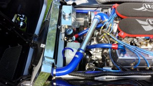
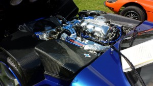
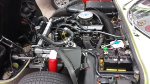
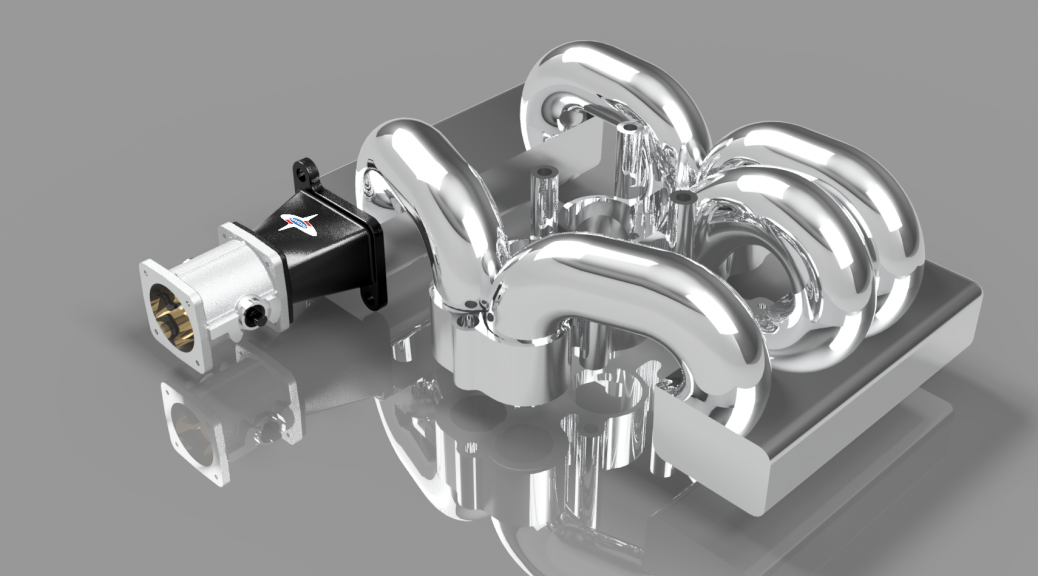
Today I collected the results of my experiment with 3D printed parts. In a previous post I showed how I was designing a revised inlet system using two new throttle bodies to replace the standard Range Rover part. The design has matured a little and the geometry is now fixed so it would be great to get the parts manufactured.
The final adapter design in Fusion 360
This is a screen capture from the Fusion 360 CAD program showing the adapters in place on the manifold.
This is the result, printed here on the Isle of Wight by Island 3D Printing.
And here’s one of the adapters with a throttle body attached. The oil filler tube will have to be relocated before I can mount the other side.
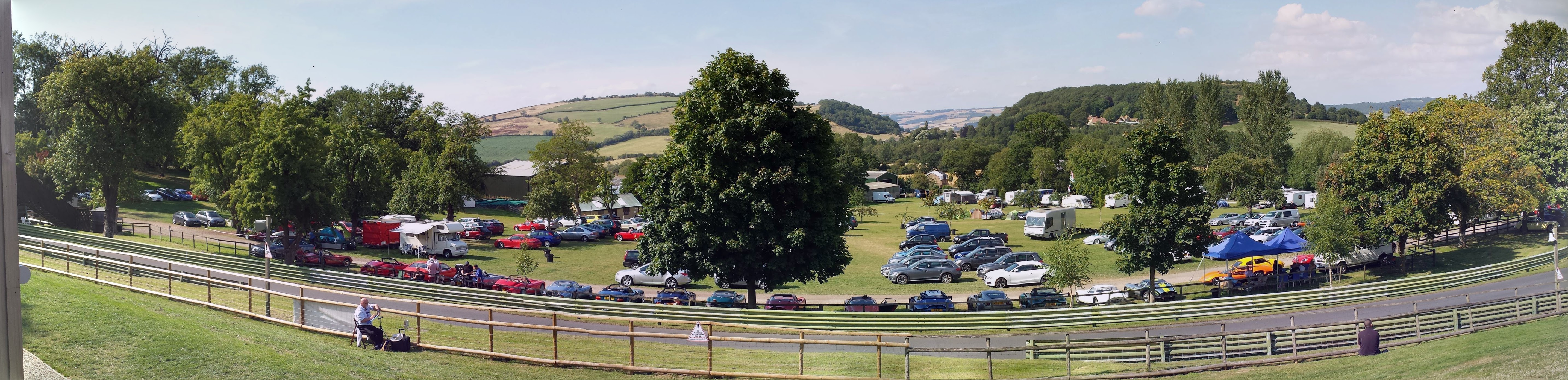
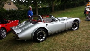
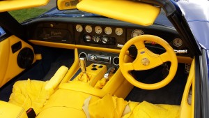
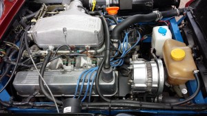
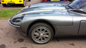
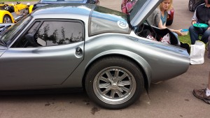
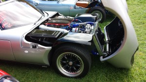
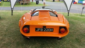
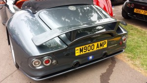
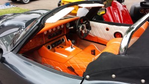
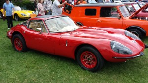
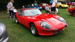
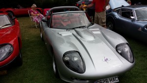
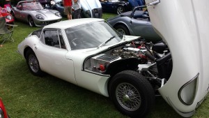
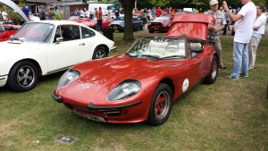
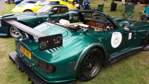
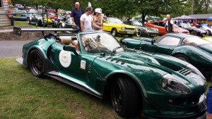
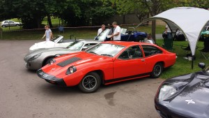
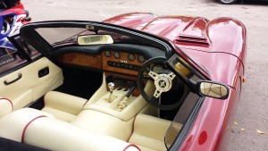
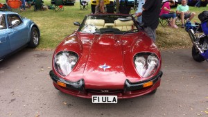
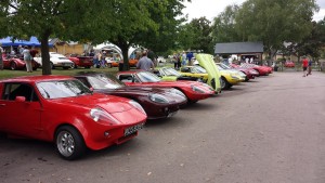
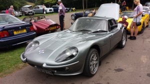
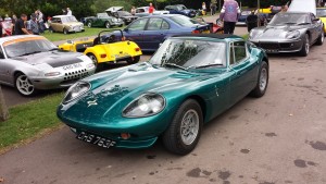
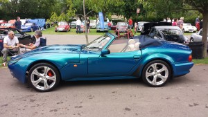
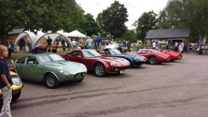
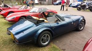
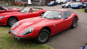
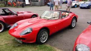
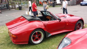
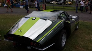
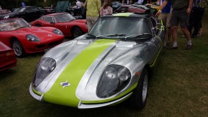
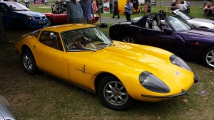
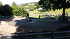
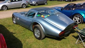
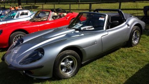
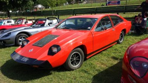
What a great weekend that was! Here on the island I never get to see any other Marcos cars, so to see more than 50 in one place was a huge thrill! But it’s not just the cars, the owners are some of the nicest people you could hope to meet.
The venue is rather special too…
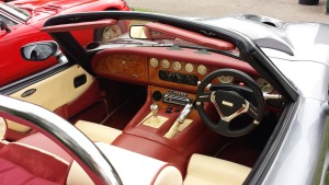
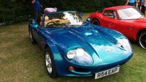
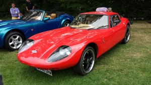
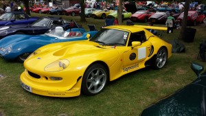
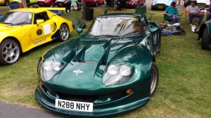
Here’s a random selection of pictures from the event, not too bad for a mobile phone…
Sorry that I’ve been so quiet for the last couple of months. Progress on the car has been minimal due to other commitments. While I’m out of the country often it been impossible to get anything done.
I’m sure you would prefer to see pictures of the Mantula, but nothing new to show yet. However time hasn’t been totally wasted as I prepare to design the changes for the inlet system.
Fusion 360
The image below shows the work-in-progress on two fronts. The first front is learning to use a 3D parametric CAD system. I chose Autodesk’s Fusion 360 Ultimate. It’s really easy to learn, has an appropriate feature set and is affordable. For any ‘hobbyist’ it is free, at least for now… Better even than that it’s a joy to use. I think I’m becoming addicted.
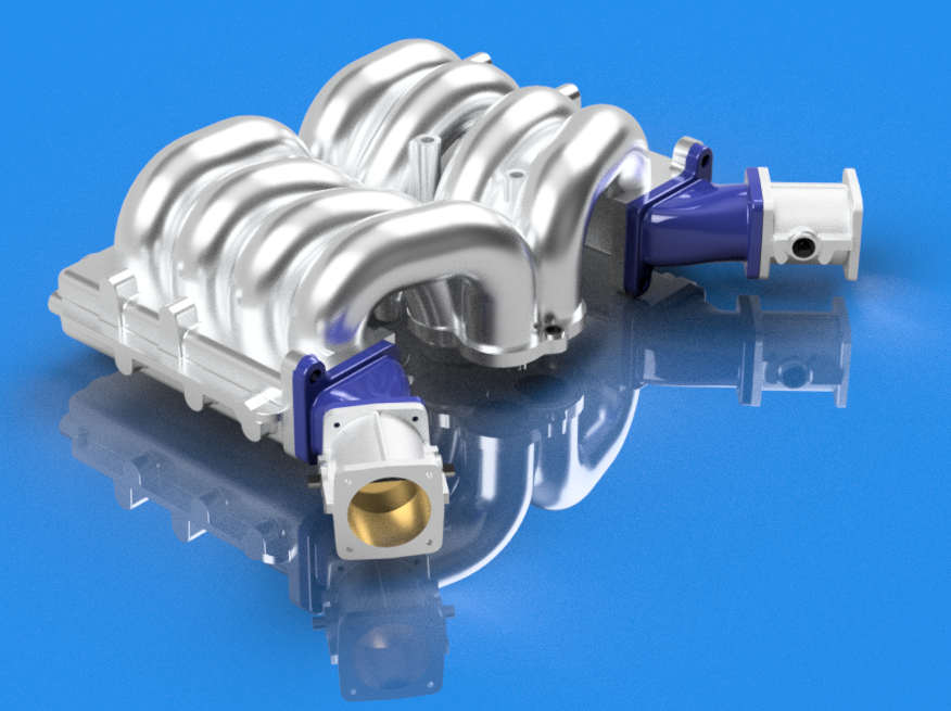
Second front is the design of the inlet system.
The model still has a long way to go, but I think it’s worth the effort. Drawing the plenum has been a real challenge due to its totally asymmetric, organic design and overall complexity. As you can see I still have three more inlet runners to model, plus all of the fixing points.
The next part is the black mounting adapter with the Marcos logo. This will be 3D printed once the final design has been fixed. The current version needs some rework for clearance. Of course I will only know the effect on performance once I get to run the engine.
The last part shows one of the Jenvey 48mm throttle bodies. This has been modelled to 0.01 mm accuracy to ensure that the throttle linkage works first time. A really great feature of Fusion 360 is the ability to design joints that are limited to a realistic range of movement. So far I have the throttle opening the correct 83 degrees. This will be eventually joined to the main link mechanism, again with accurate movement limits.
For the next few weeks I will be completing this design work. Then I’ll send the CAD files to a local machine shop for manufacture.
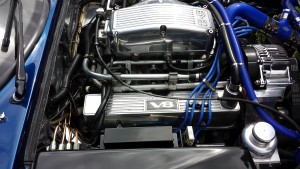
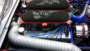
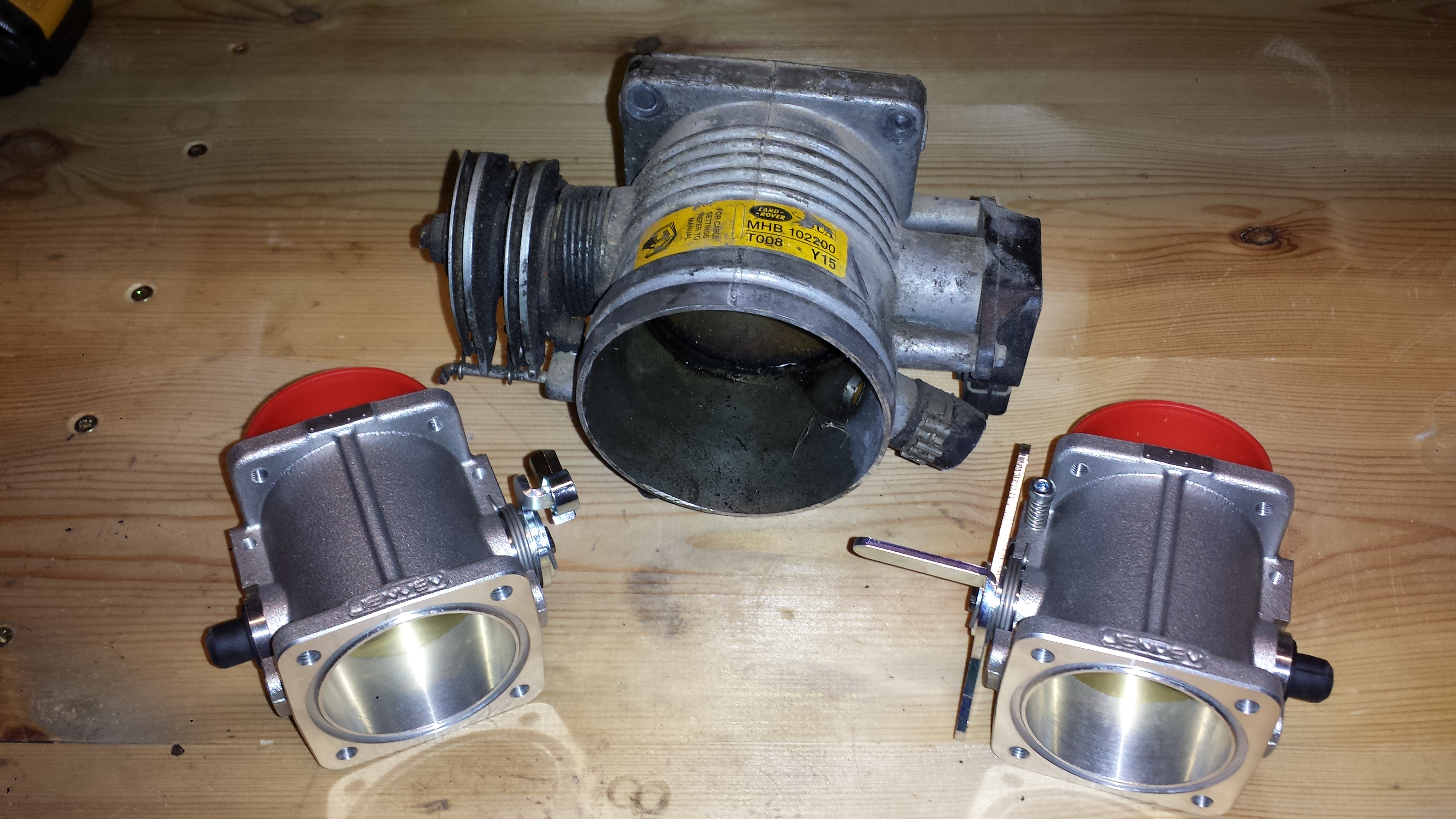
Jenvey throttle bodies
As mentioned above I’m going to use the excellent Jenvey throttle bodies to replace the original Range Rover item. Here’s a comparison.
Two smaller throttles should give better response than a single large throttle. I can’t wait to find out!
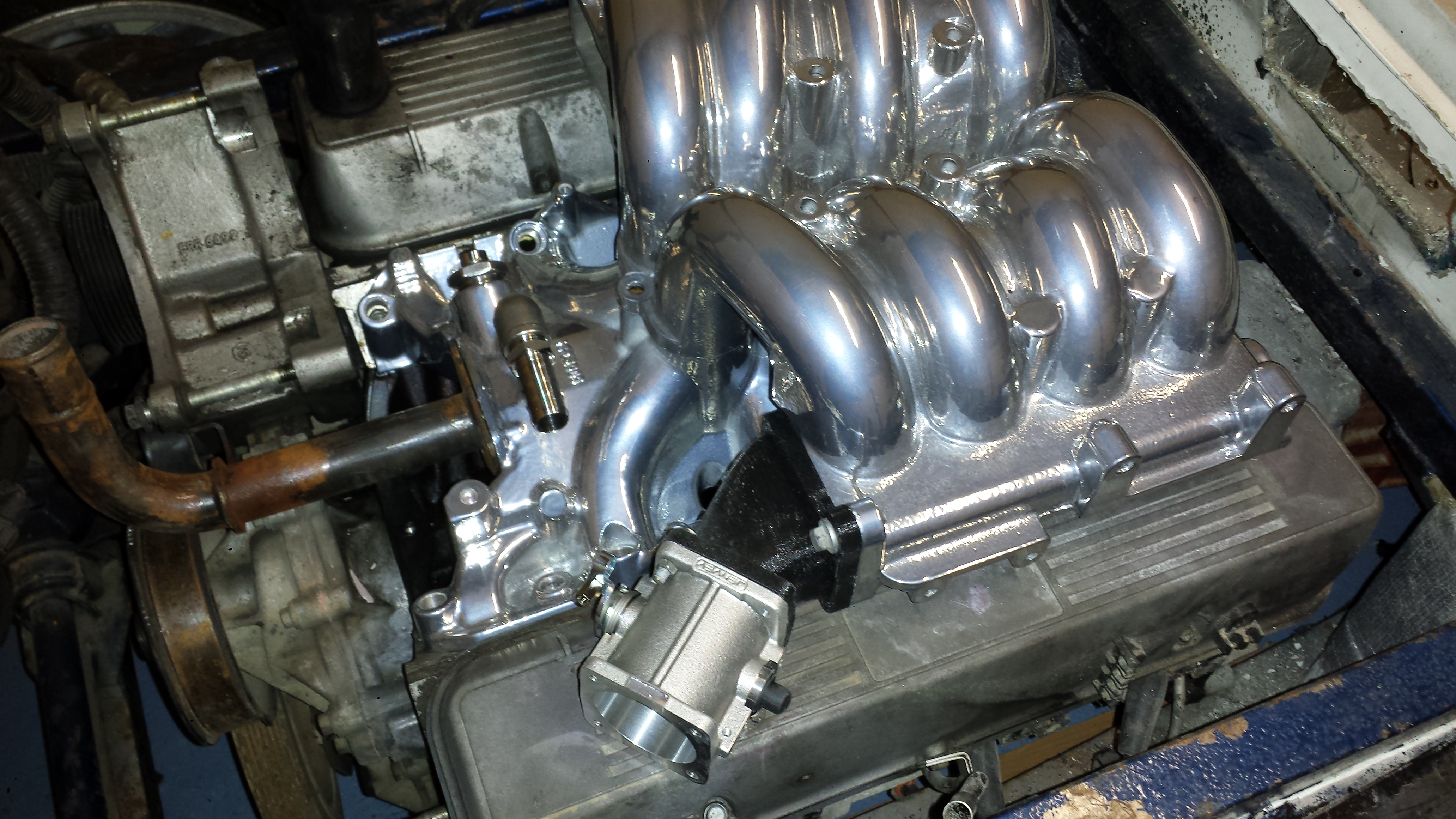
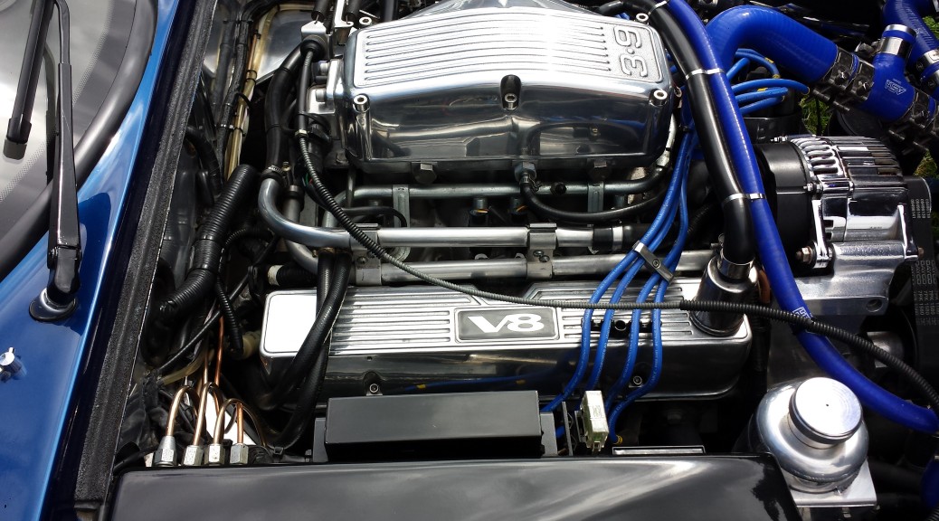
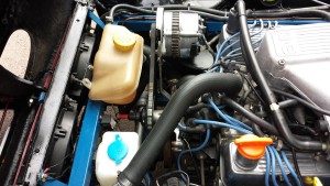
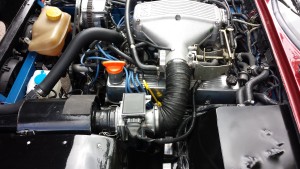
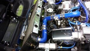
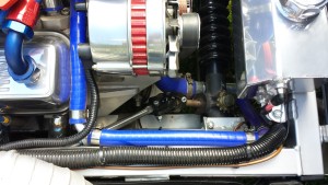
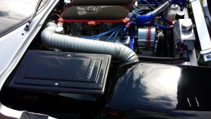
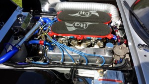
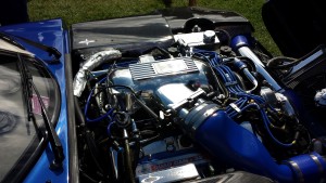
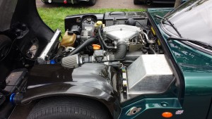
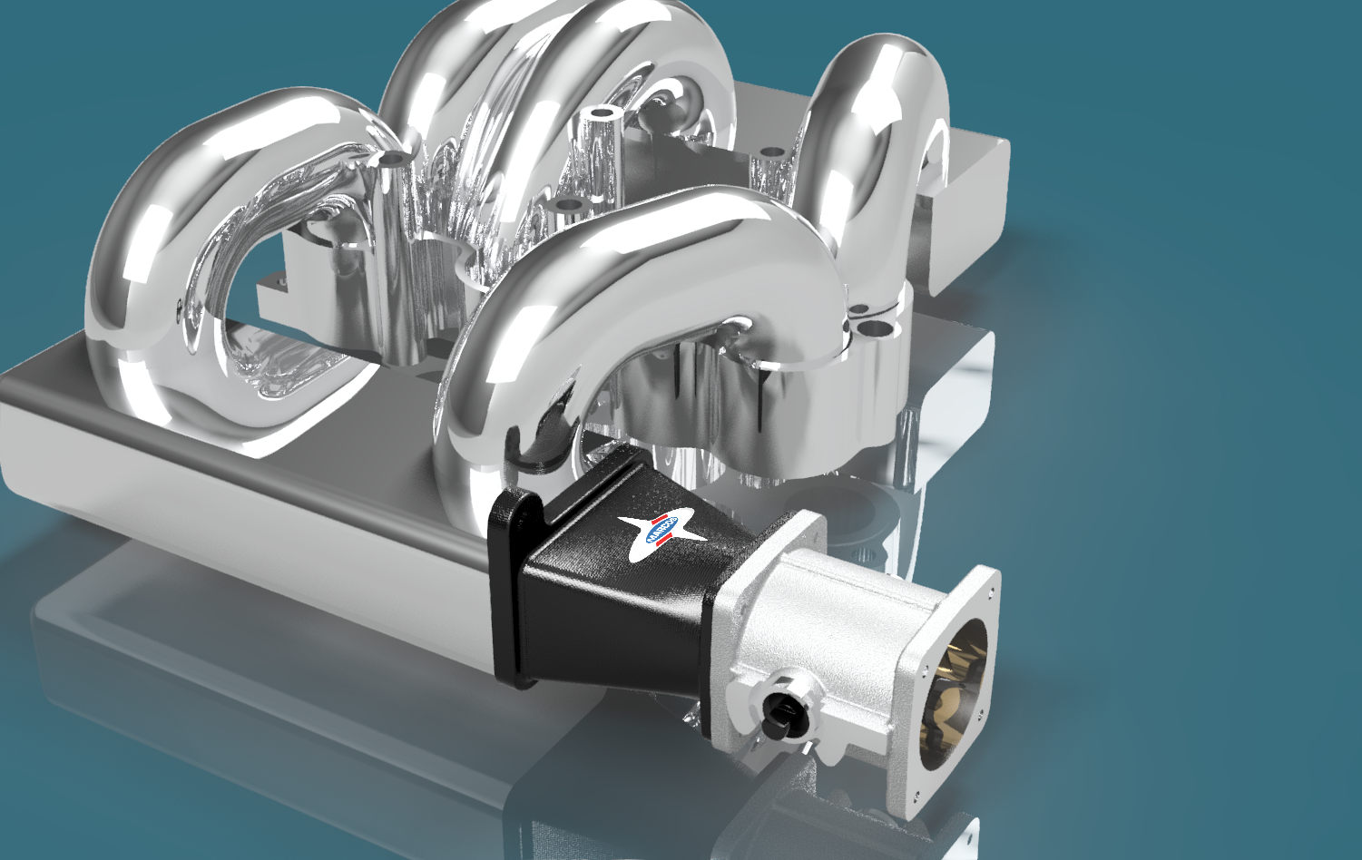
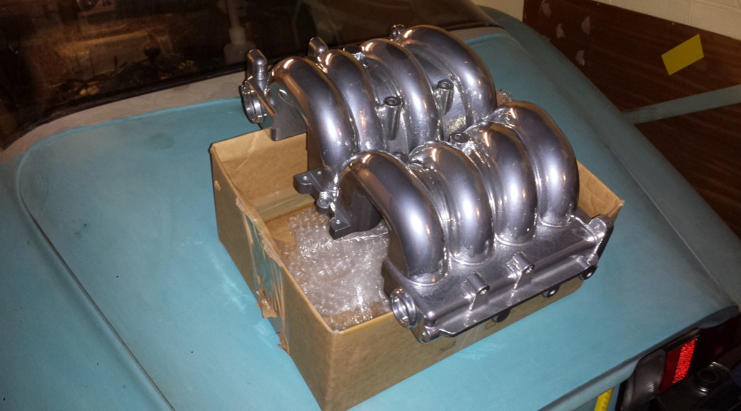
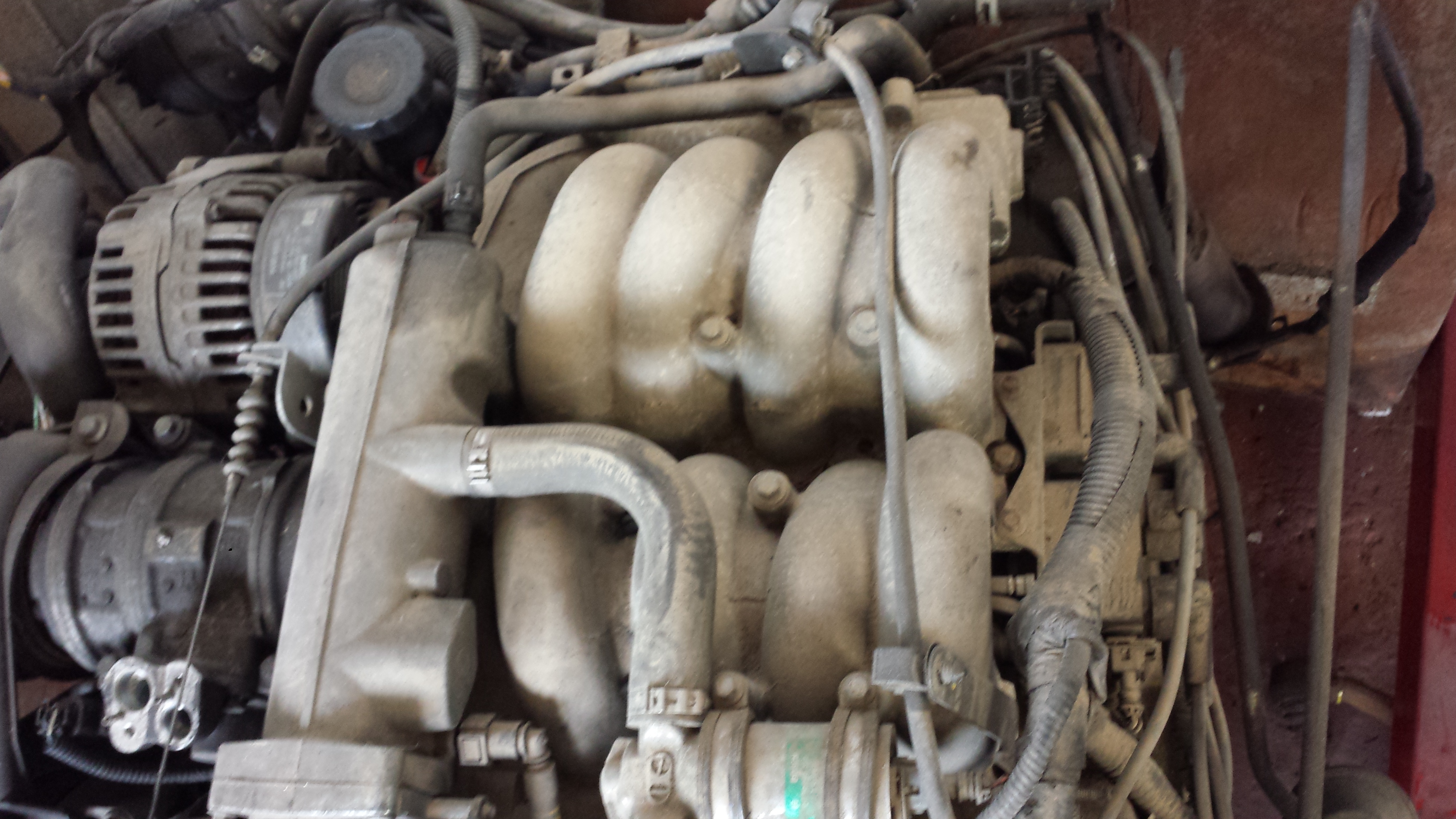
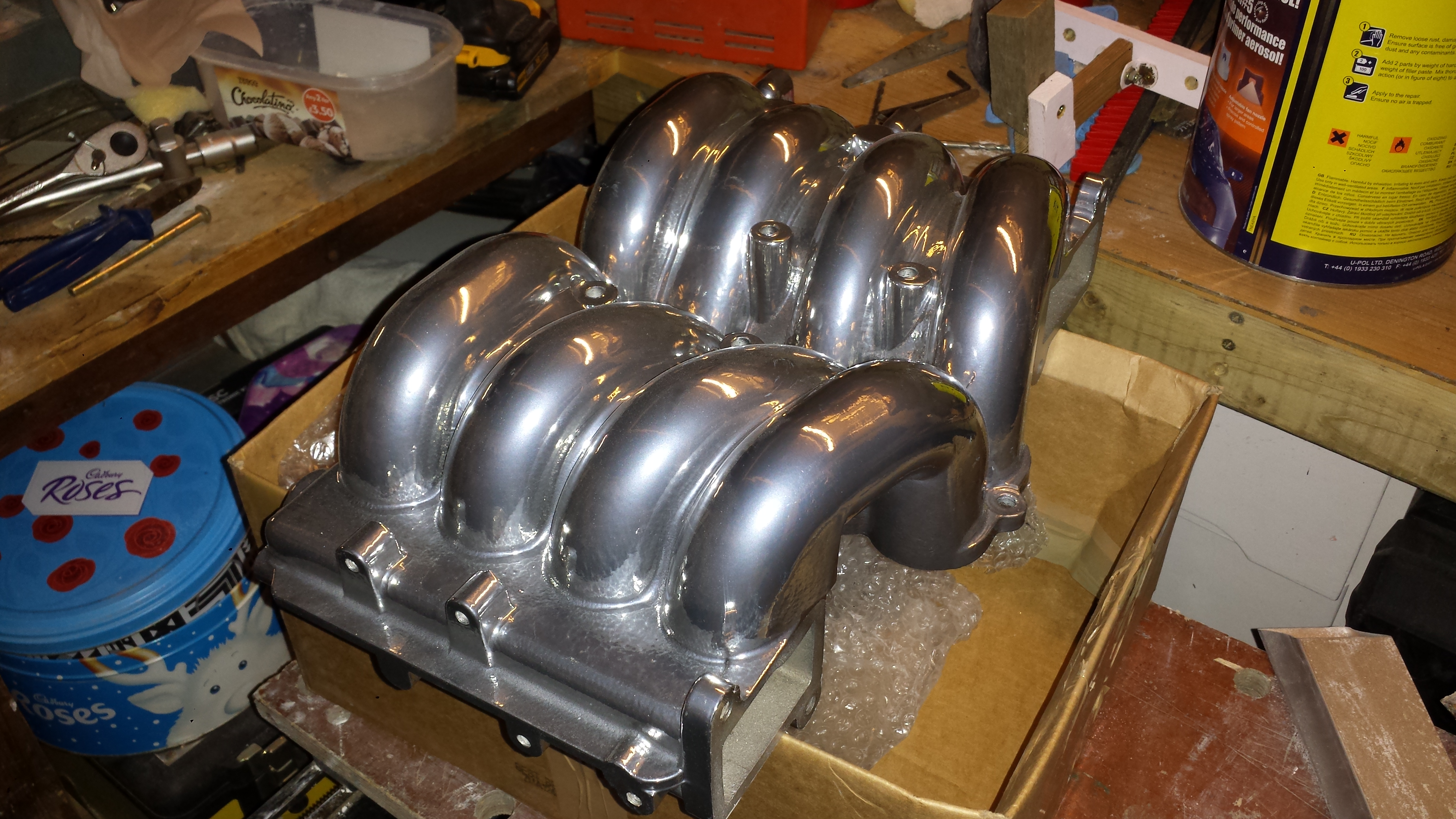
Sometimes it’s nice to see a part of the car looking good even when everything else still looks rough. That was the reason for getting the top half of the inlet manifold powder coated in chrome effect.
Before and after…
I think it looks pretty good, so thanks to Bret at Vectis Powder Coating for a job well done.
The lower half of the manifold is being machined by SeaTek Engineering in Cowes. This will re-align the water outlet to take a more direct route to the heater matrix.
You may wonder why I’m putting so much effort into the design of an air conditioning system when there is so much to be done to get the engine re-configured and running. Maybe I’ve asked myself that question too, but it has to be the right way to go. Based on the tales of stuffy, overheated Marcos interiors I know that I would hate driving in those conditions. I’m not a lover of excessive heat, anything over about 28 deg C I find uncomfortable. Also I want this Mantula to be a real GT car for long distances, not just short sprints.
Clearly that leaves me with three options, a conversion to soft-top, a Webasto type sunroof or a really powerful air conditioning system. I couldn’t go the soft top route because I just don’t want to lose the coupe body shape. Maybe the Webasto would be quite nice, but would it really keep me cool with all of that engine heat? That leaves the air conditioning as the way ahead.
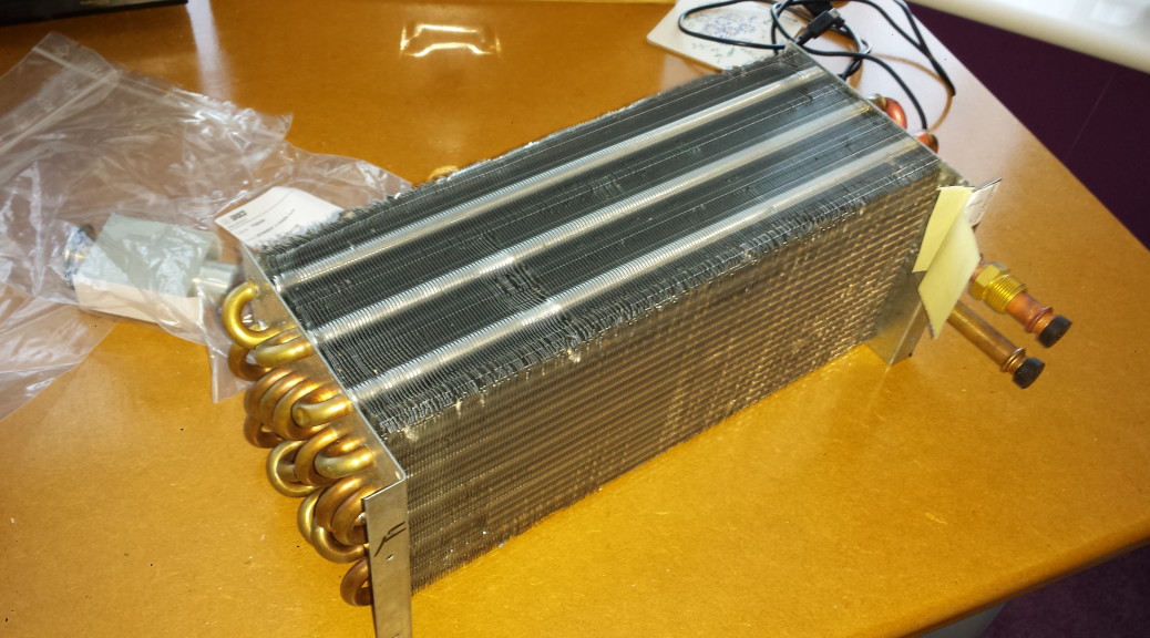
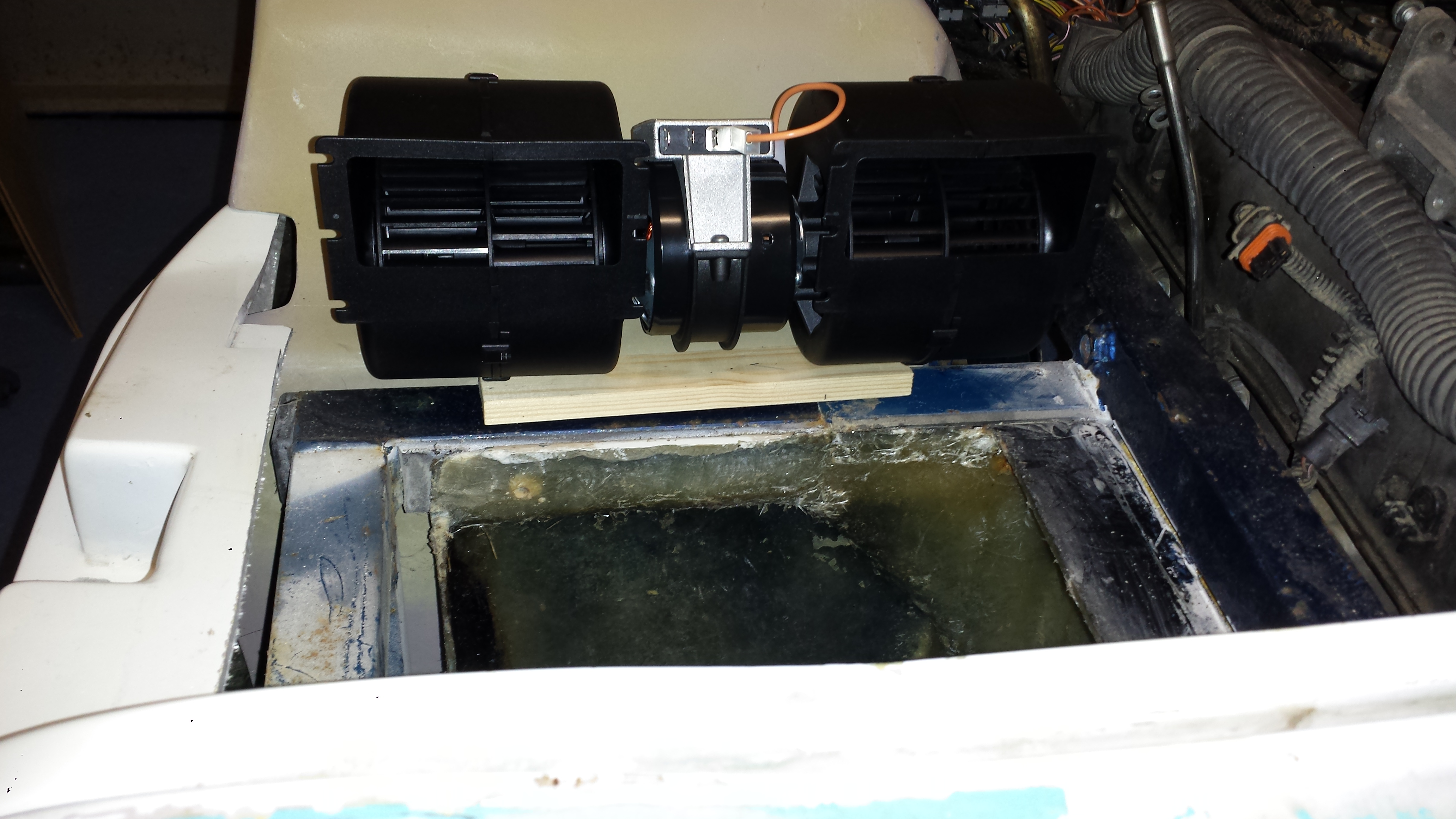
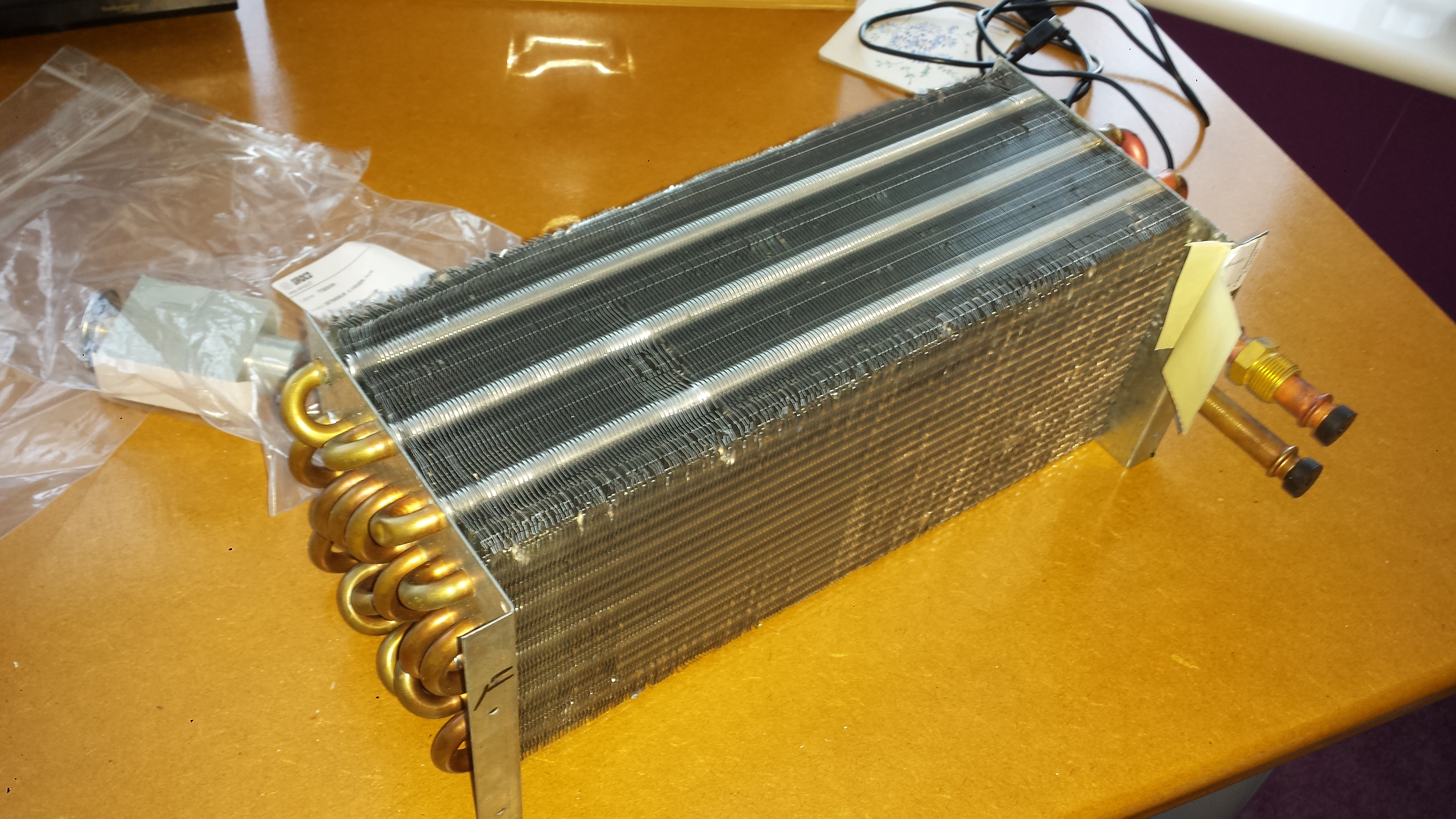
The design of the a/c system has now been decided, a double blower will force the filtered incoming air through a large evaporator to be cooled and dried. The air then flows through the heater section where an adjustable gate directs the flow through the heater matrix or the bypass duct. From there it cools or heats the cabin via electronically controlled valves.
The SPAL blower is just the right dimensions for the air con box.This Sirocco evaporator is rated at 9.6 kW!
The remainder of the system comprises the engine mounted compressor the condenser and the receiver/drier. All of these parts are to Ranger Rover spec or higher.
From my calculations the system should be more than capable of keeping the tiny Marcos cabin cool even on the warmest days. I’ll also use some Zircotec flexible ceramic heat shielding to prevent heat soak.
Just to make the whole thing even more complicated this will be a real climate control system with temperature, sunlight and humidity sensors. All vents, the compressor clutch and the blower motor will be controlled by an Arduino processor.
A long time since my last update. Not so much progress as I’ve been working in Paris for three of the last four weeks. The work on the pattern for the air con system has had a couple of setbacks due to the way I constructed the shaped top part. The PU foam went soft after application of the filler. So although I had the shape I wanted, it was too fragile to finish to my satisfaction. I think I have been able to repair the soft areas now, but it wasted a lot of time and effort.
The design is also evolving. The removable lid will be fixed at the sides rather than the top. Hopefully that change will make it simple to fit the blower, evaporator and matrix.
It’s important to give the air an unrestricted flow into the air con box. The initial plan was to connect some 100mm hose, but that won’t be ideal due to limited space. The engine air inlet also has to occupy a the same space. My next crazy idea is to build a double-skinned top to the near-side inner wing and route the air through that… Again this will all be done in carbon-fibre.
Uni-Mould kit
The mould making materials arrived this week. I’m using the large Uni-Mould starter kit from Easy Composites. This includes a huge 25kg drum of tooling resin along with gel-coat, bonding resin and all the glass fibre mat I will ever need. With that and all of the parts I’ve been accumulating I’ve almost run out of space to actually make the moulds!
That’s all for this instalment. It will be a while before I can press-on with the mould making.
Happy New Year to you all. 2015 will be an important year for the Mantula. The initial strip-down and preparation will take a few more months, but then things will begin to move forward at a faster pace.
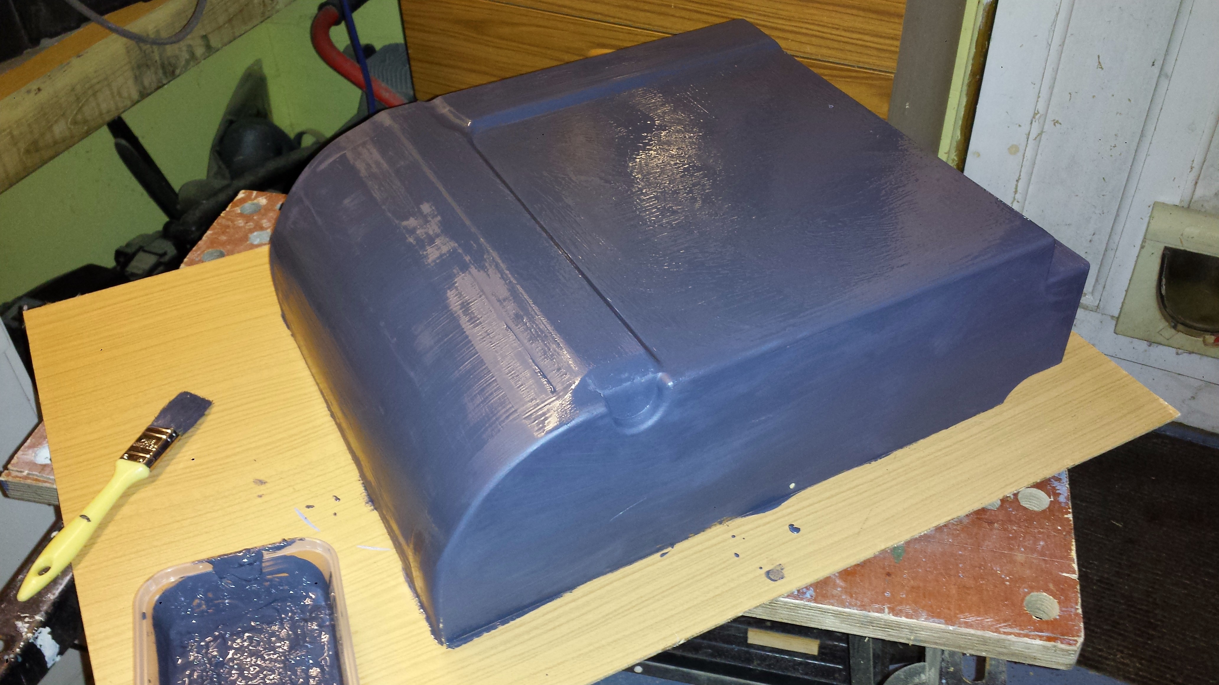
In the meantime I will continue with some of the various design tasks. In my last post I started work on the A/C housing pattern. This work continued over the Christmas break. The general shape is almost complete, and it’s looking just as I intended – which is a nice surprise!
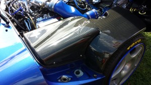
The underside is shaped to sit on the chassis rails and clear the foot-well tub which sits slightly higher on my car.
Underside of the A/C housing pattern.
The semi-circular indent is there to clear the mounting point for the left-hand steering Rose joint (Heim joint). Despite carefully measuring the MEKP catalyst it still started to cure before I had finished applying all over, hence the rather rough finish. No problem though as this primer is easy to sand smooth.
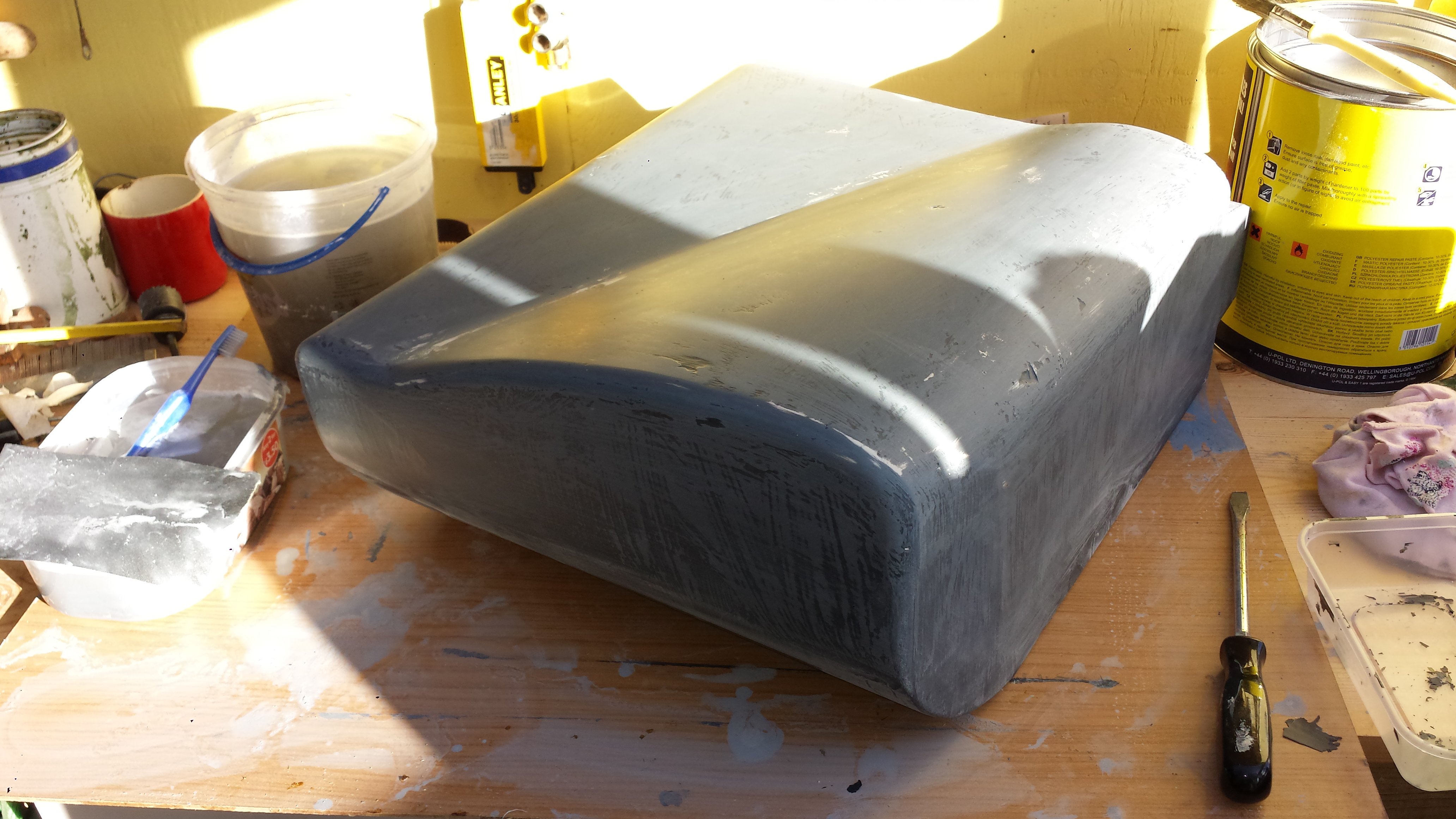
For the top surface I wanted to follow the internal shape of the bonnet. I won’t go into detail on how I achieved this using expanding foam. To be honest it was a messy disaster, but we live and learn…
However it was recoverable so I now have this shape…
Top of the A/C housing pattern
This is close to completion, but it still needs to have the air inlet moulded into the front. Clearly there are still imperfections in the surface, but these will soon be filled.