Category Archives: Composites

Who said this would be easy?

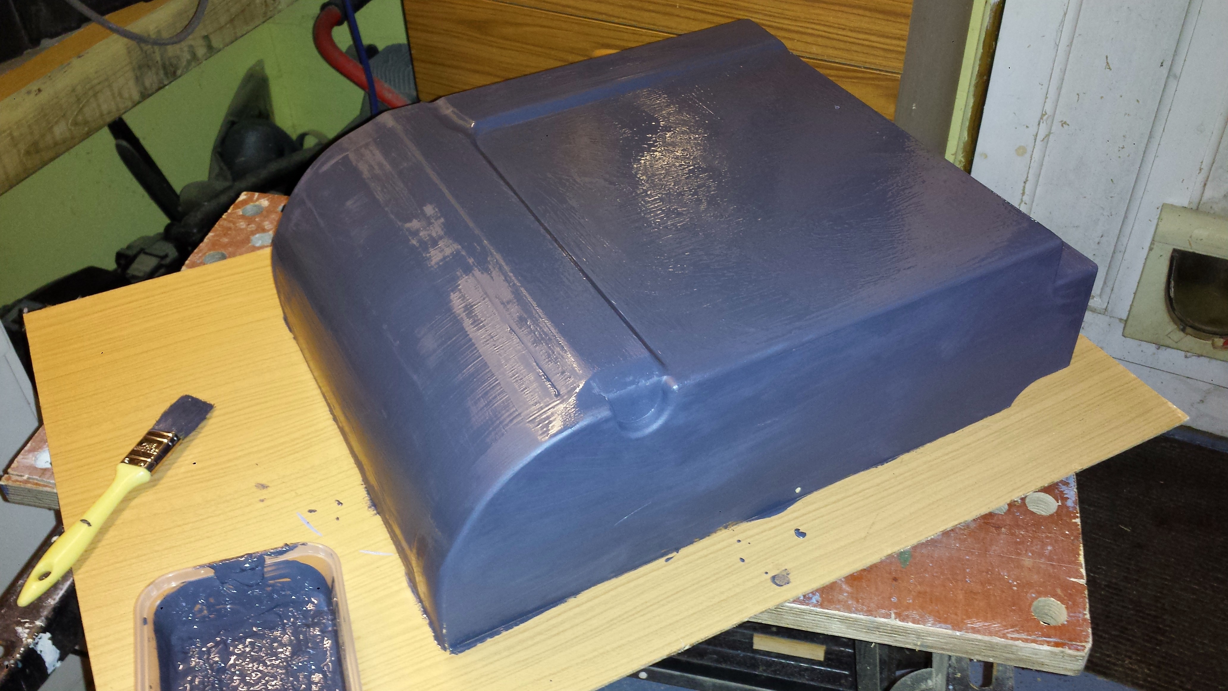
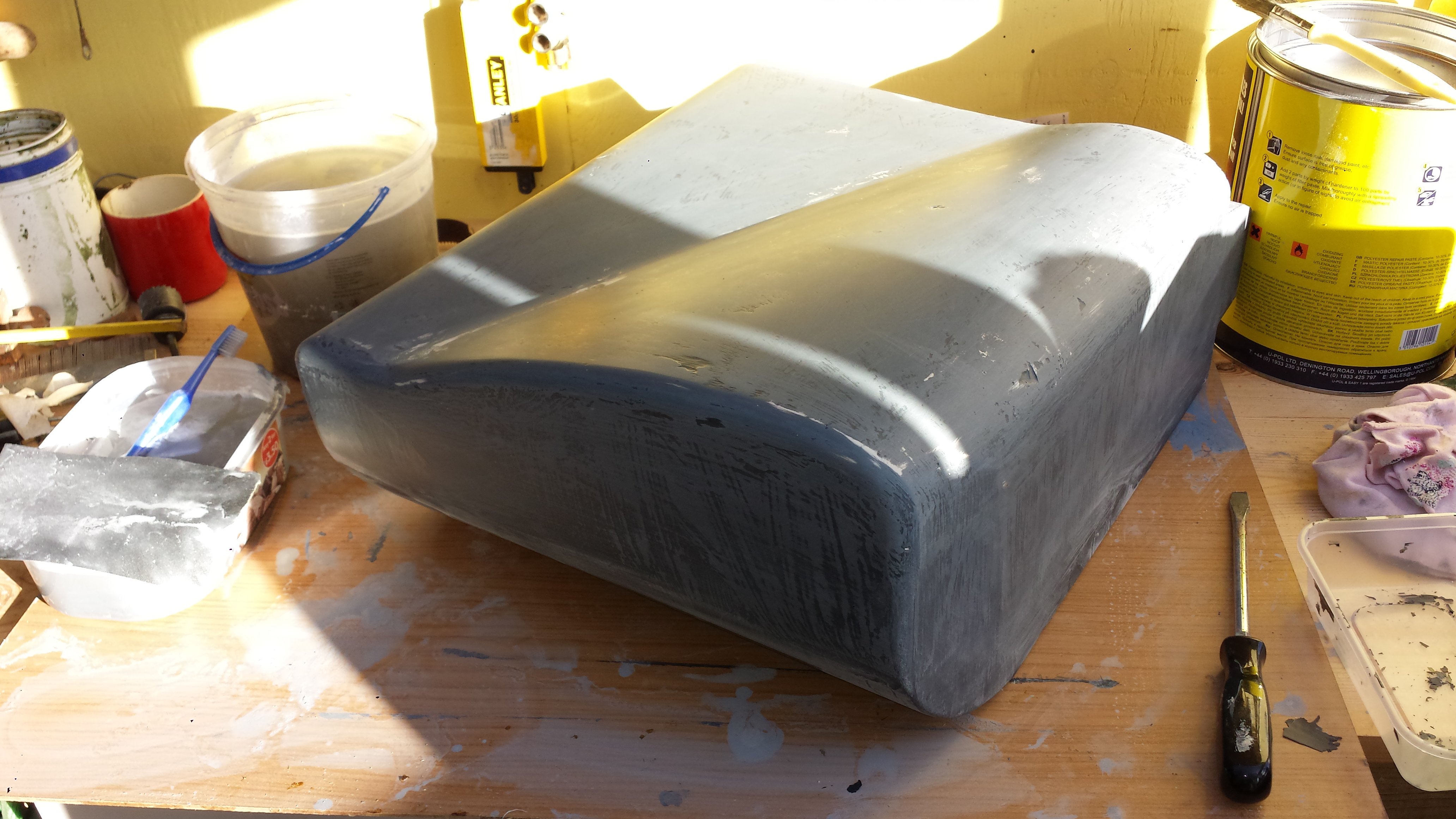
A long time since my last update. Not so much progress as I’ve been working in Paris for three of the last four weeks.  The work on the pattern for the air con system has had a couple of setbacks due to the way I constructed the shaped top part. The PU foam went soft after application of the filler. So although I had the shape I wanted, it was too fragile to finish to my satisfaction. I think I have been able to repair the soft areas now, but it wasted a lot of time and effort.

The design is also evolving. The removable lid will be fixed at the sides rather than the top. Hopefully that change will make it simple to fit the blower, evaporator and matrix.

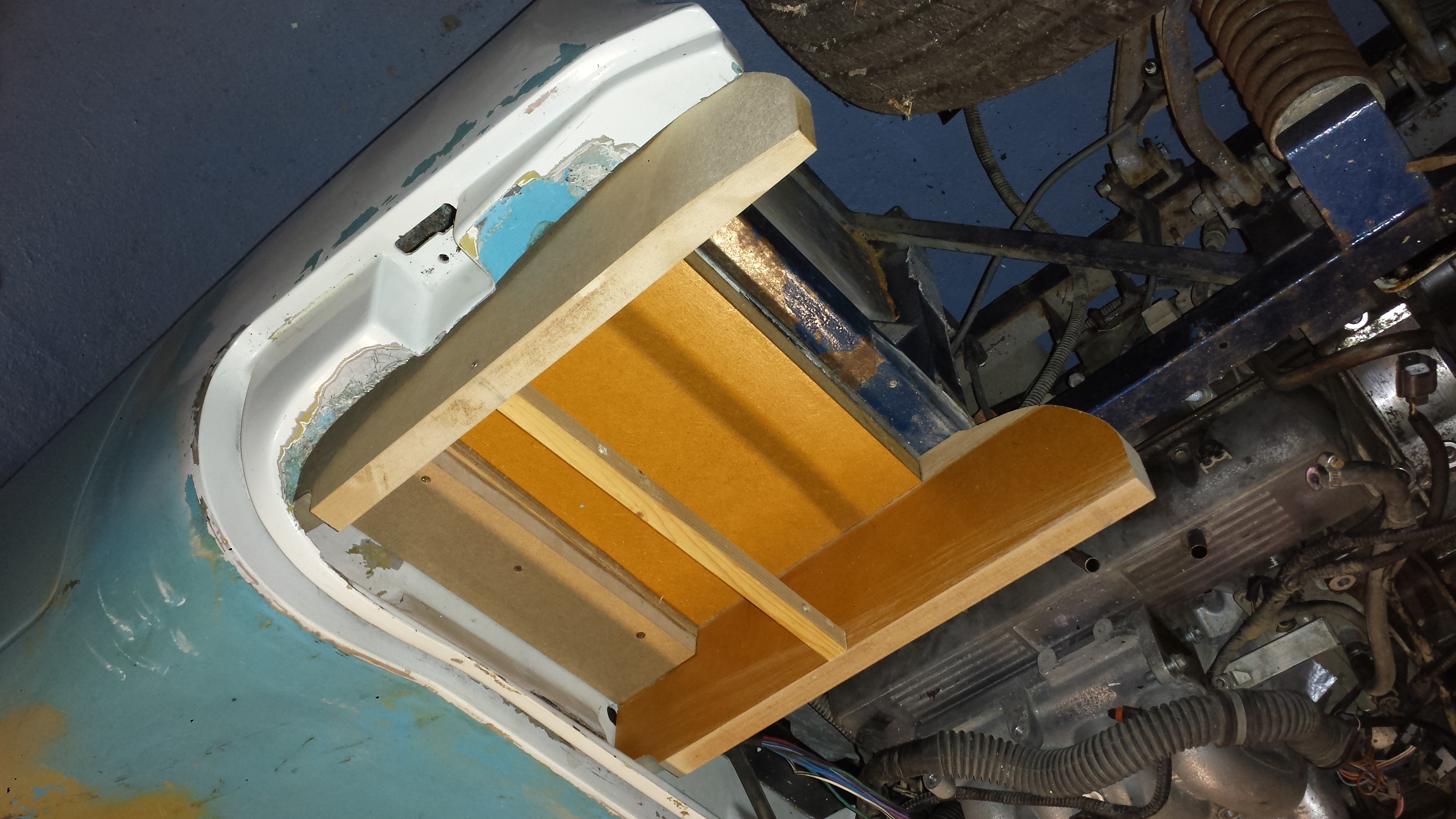
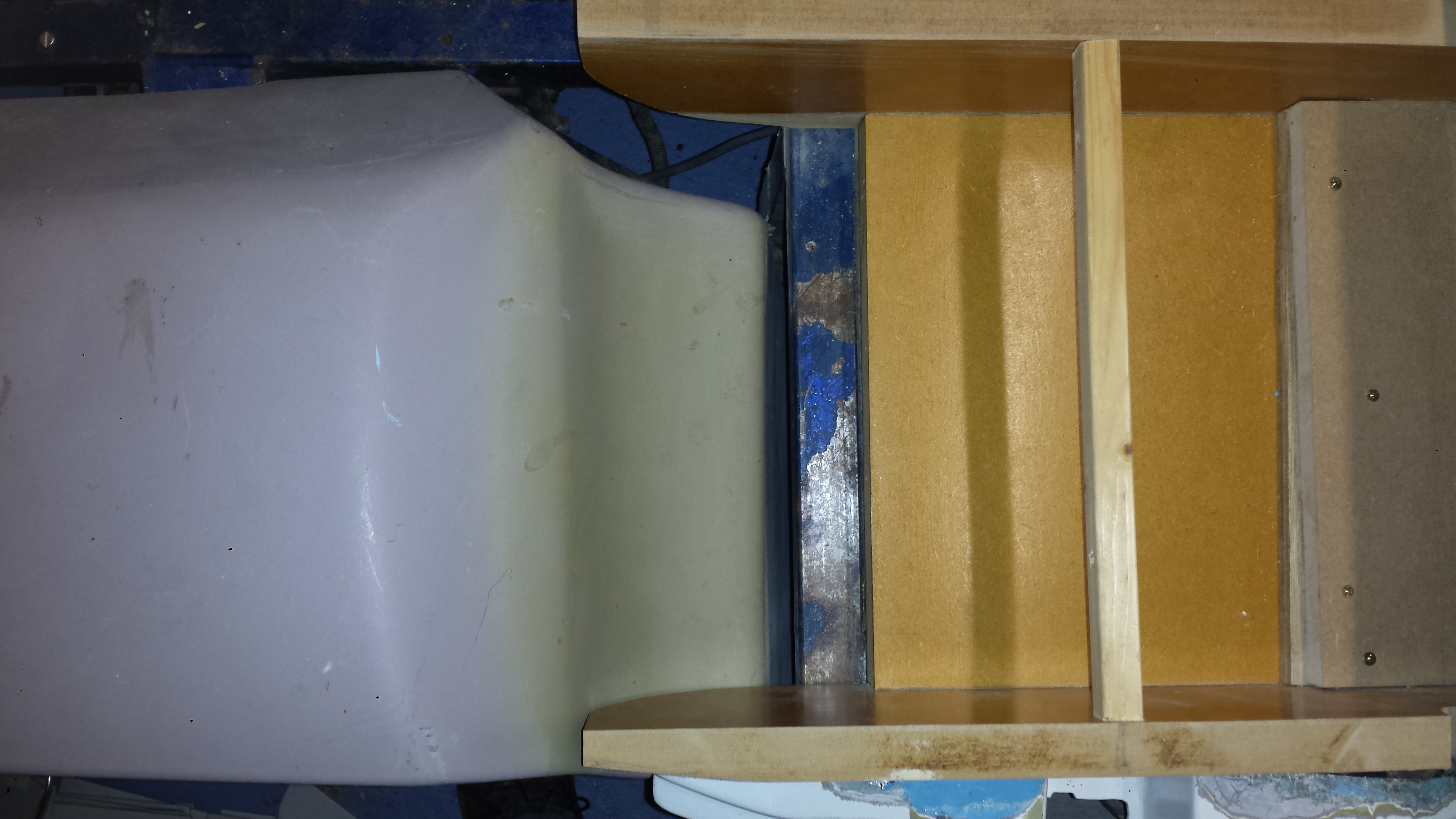
It’s important to give the air an unrestricted flow into the air con box. The initial plan was to connect some 100mm hose, but that won’t be ideal due to limited space. The engine air inlet also has to occupy a the same space. My next crazy idea is to build a double-skinned top to the near-side inner wing and route the air through that… Again this will all be done in carbon-fibre.

Uni-Mould kit

The mould making materials arrived this week. I’m using the large Uni-Mould starter kit from Easy Composites. This includes a huge 25kg drum of tooling resin along with gel-coat, bonding resin and all the glass fibre mat I will ever need. With that and all of the parts I’ve been accumulating I’ve almost run out of space to actually make the moulds!

That’s all for this instalment. It will be a while before I can press-on with the mould making.

MDF, foam and filler – part 2

Happy New Year to you all. 2015 will be an important year for the Mantula. The initial strip-down and preparation will take a few more months, but then things will begin to move forward at a faster pace.

In the meantime I will continue with some of the various design tasks. In my last post I started work on the A/C housing pattern. This work continued over the Christmas break. The general shape is almost complete, and it’s looking just as I intended – which is a nice surprise!

The underside is shaped to sit on the chassis rails and clear the foot-well tub which sits slightly higher on my car.

Underside of the A/C housing pattern.

The semi-circular indent is there to clear the mounting point for the left-hand steering Rose joint (Heim joint). Despite carefully measuring the MEKP catalyst it still started to cure before I had finished applying all over, hence the rather rough finish. No problem though as this primer is easy to sand smooth.

For the top surface I wanted to follow the internal shape of the bonnet. I won’t go into detail on how I achieved this using expanding foam. To be honest it was a messy disaster, but we live and learn…

However it was recoverable so I now have this shape…

Top of the A/C housing
Top of the A/C housing pattern

This is close to completion, but it still needs to have the air inlet moulded into the front. Clearly there are still imperfections in the surface, but these will soon be filled.

MDF, foam and filler – part 1

I’ve started making the pattern for the air conditioning housing. It a box made of 25mm  MDF that is built in position on the car. It probably didn’t need to be that thick as it makes for a very heavy construction, but it’s solid and should remain in shape as its gets worked into its final form. It also has the advantage of allowing deep features to be carved into the surface.

While the base of the box has to fit to the chassis steelwork, the upper section can be more stylish. Of course it needs to fit under the bonnet, but that should help to define the general shape.

At the front of the box the idea was to give it the rounded profile similar to the a Marcos pedal box. With that in mind I transferred the curve from the inner wing onto the box side. I adjusted this to be little more uniform and to give some clearance. Then I transferred the same curve to the outside. With both parts cut it I assembled the box. So far it’s all looking good.

Sides and base connected

That will never fit…

Once again the “informal” Marcos approach to mould making has caught me out. The inner wing profile is all over the place. The curve fits on the inside edge but is a least 20 mm out on the outside. That means the inner wing does not fit. In the picture below you can see the gap between the inner wing and the chassis.

Outer edge pushes the inner wing forwards by 20 mm

How do I handle this? Well there are three options:

  1. Trim the outside profile by 20mm to make it fit the existing inner wing. The would make the a/c box asymmetric, but would fit any Marcos Mantula.
  2. Trim both profiles to make it fit and symmetrical. This may emphasise the asymmetry of the inner wing, but would also fit other installations. Space for the blower would be compromised.
  3. Re-design the inner wing. I was going to have to do a lot of work in this area anyway. The original wings are a very poor fit in any case.

In the the end it was an easy choice I’m going with option 3. This also has the benefit of giving the blower enough room for optimum airflow.

More in the next exciting instalment…