I’m back and planning the next stage of the build after years of apparent inactivity. Not the way I wanted it, but work has been taking far too much of my time.
The engine will be running before the end of 2024. That plan will involve some exciting new developments. So, if you’re interested in the design of a complete new CANBUS wiring system along with the latest in electronic engine management with twin drive-by-wire throttles and electronic display, keep watching for updates. There’s a lot to do…
I’ve definitely been working too much. Seven days a week with just three days off since the middle of September. One of the joys of being self-employed!
Now that the various projects are delivered I can give the Mantula the attention it deserves. This means there’s been quite a lot of progress considering this build normally progresses at a geological pace.
Much better than new
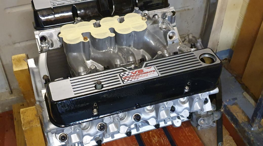
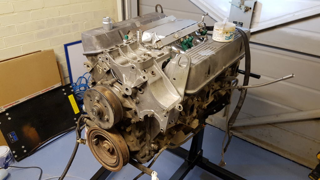
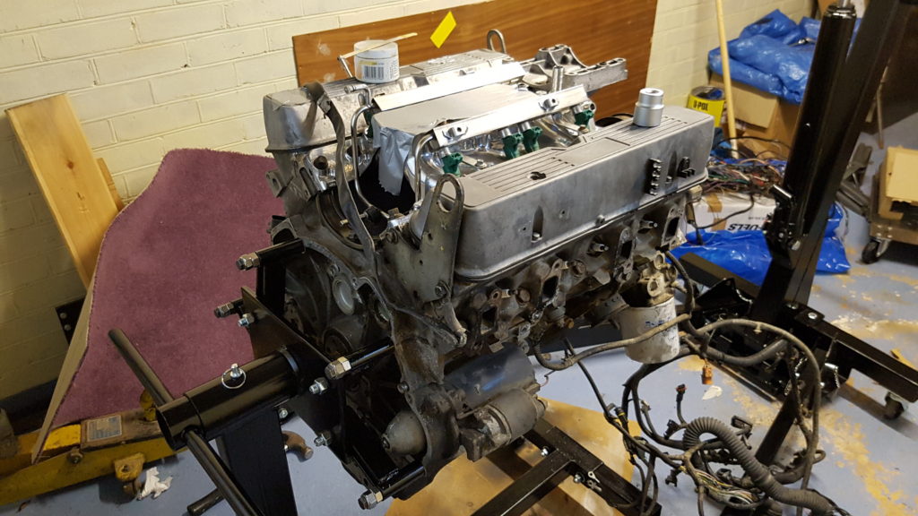
In the previous instalment I reported that the engine had been dispatched for a complete rebuild. Well, it arrived back yesterday looking very smart and probably better than new. It’s still sitting on its pallet, but I’ll get it mounted on the engine stand tomorrow. There are several important parts to attach too.
Flywheel and clutch
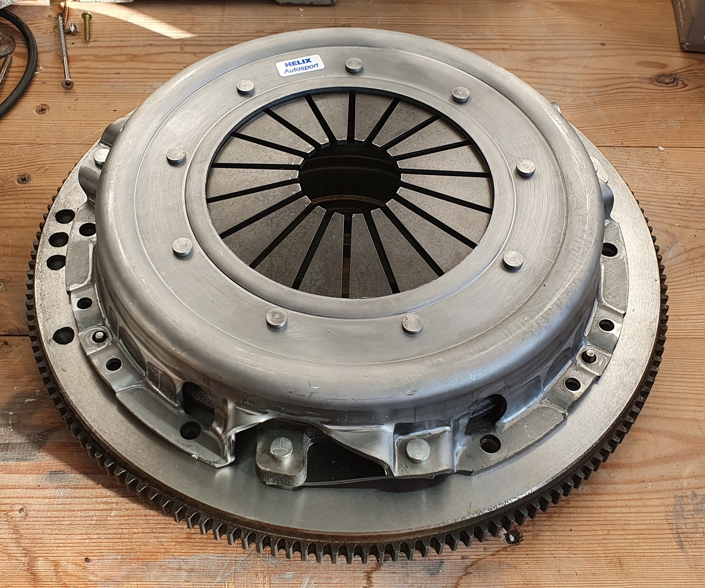
The flywheel has been modified to accept the ignition trigger ring. Once that’s mounted the up-rated clutch can be installed.
Flywheel machined to accept the trigger ring
The original clutch was Rover SD1 3.5 litre spec which wouldn’t be able to cope with the much greater torque from the modified 4.6 litre unit.
New heavy duty clutch by Helix Autosport
The front end will get a new water pump along with various brackets and sensors. More on this in a few weeks – I have to modify the serpentine belt routing so that it clears the steering linkage.
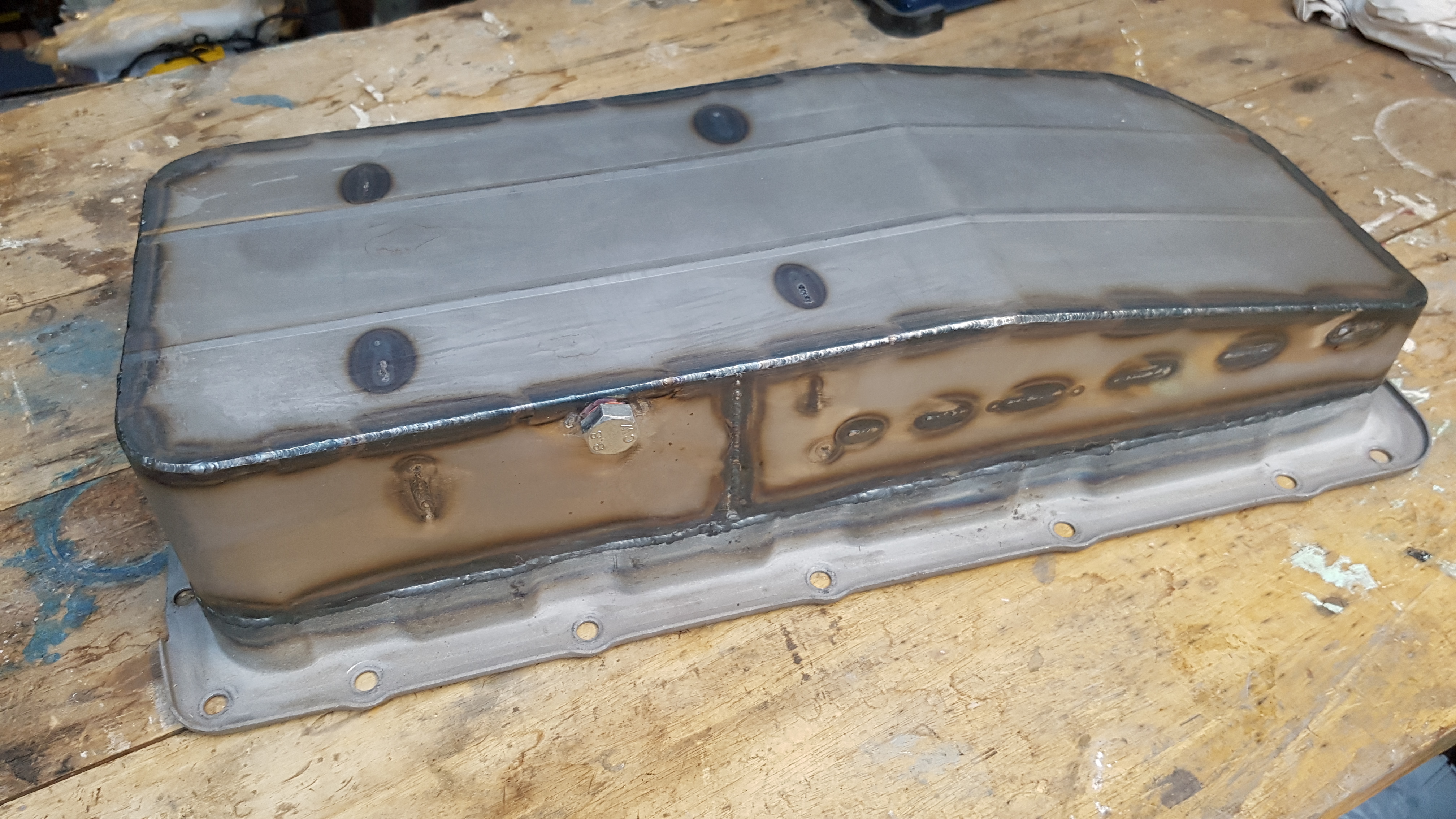
Low-profile sump
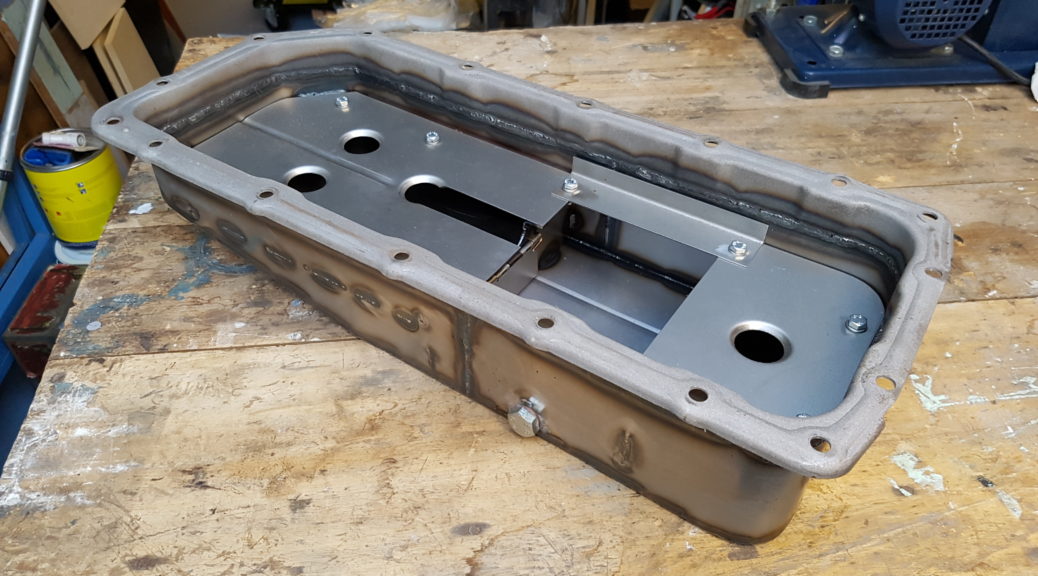
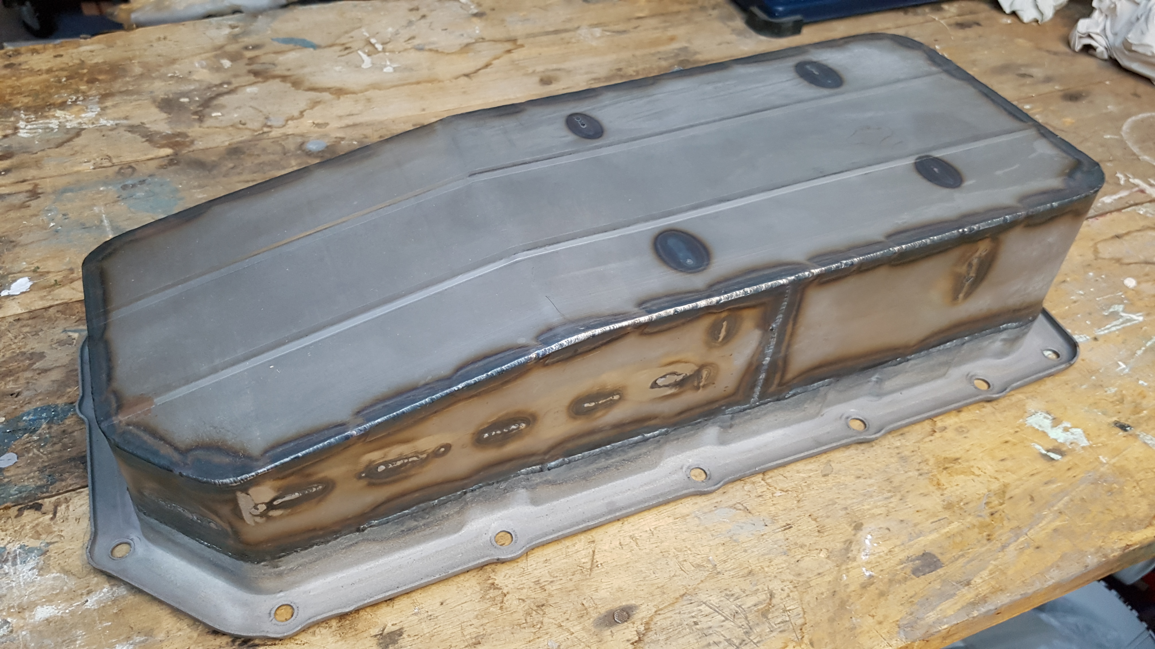
It was quite some time ago that I had the low profile sump fabricated, so it will be wonderful to finally fit the thing! That can happen as soon as it returns from getting its Zinga galvanising coating. It’ll also have an abrasion resistant ceramic coating. I’m using the sump as a practice for getting the chassis treated.
Low profile baffled sump
When everything’s fitted I’ll squirt some Double TT into each cylinder to prevent possible condensation rust damage until first start some time next year.
Chassis modifications
The chassis is booked-in for modification during the second week of January. I still have work to do on the rear end design where I’m diverging from the standard Marcos IRS set-up a little. The 3D CAD drawing will be finished next week. I’ll then get the new suspension mounts and various brackets cut out on a CNC plasma cutter.
Inlet manifold design changes
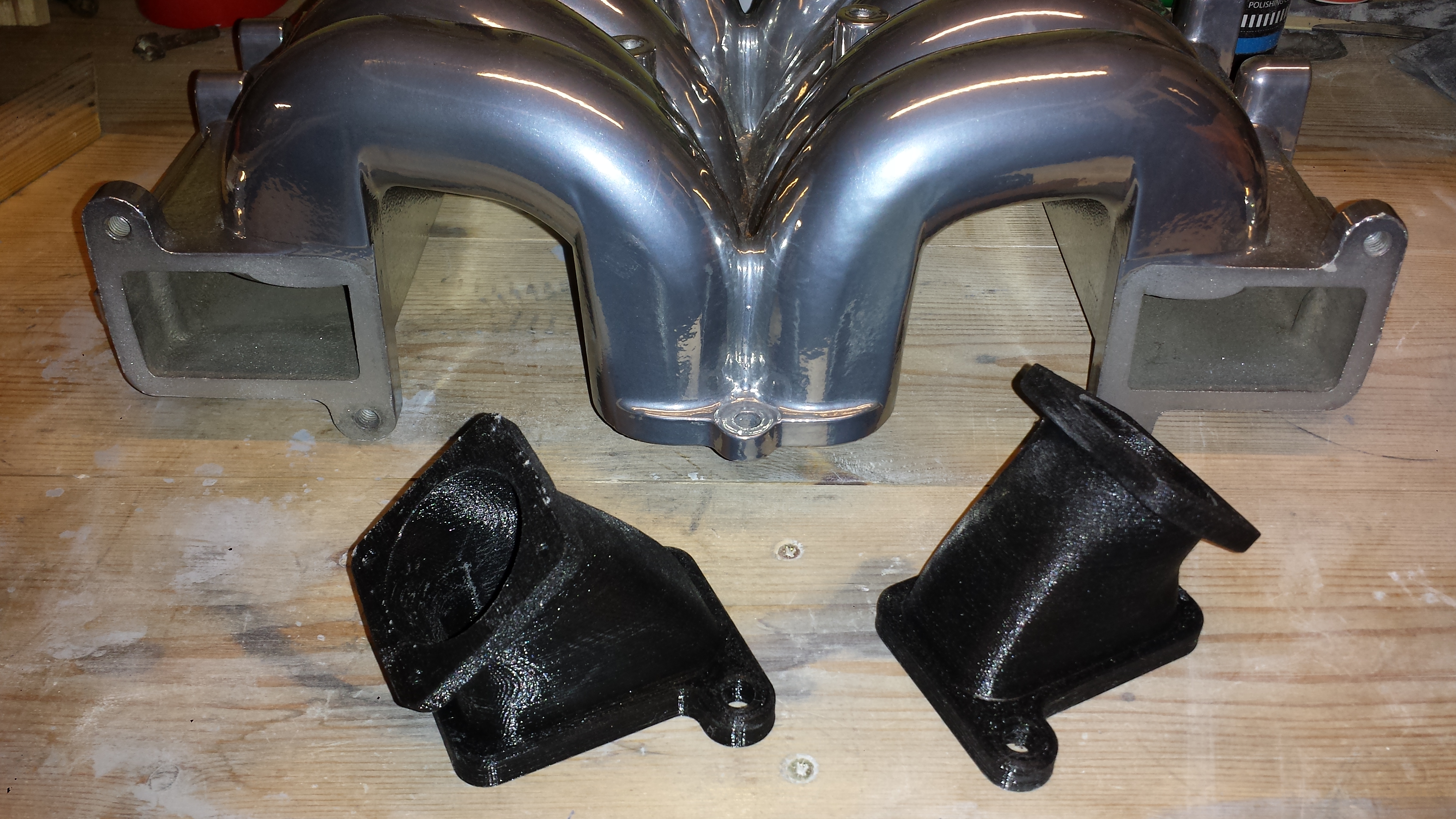
Some time ago I showed the designs for the Jenvey throttle body adapters which I had 3D printed here on the Island.
Original undersized adapterInlet adapter in position on the Thor manifold
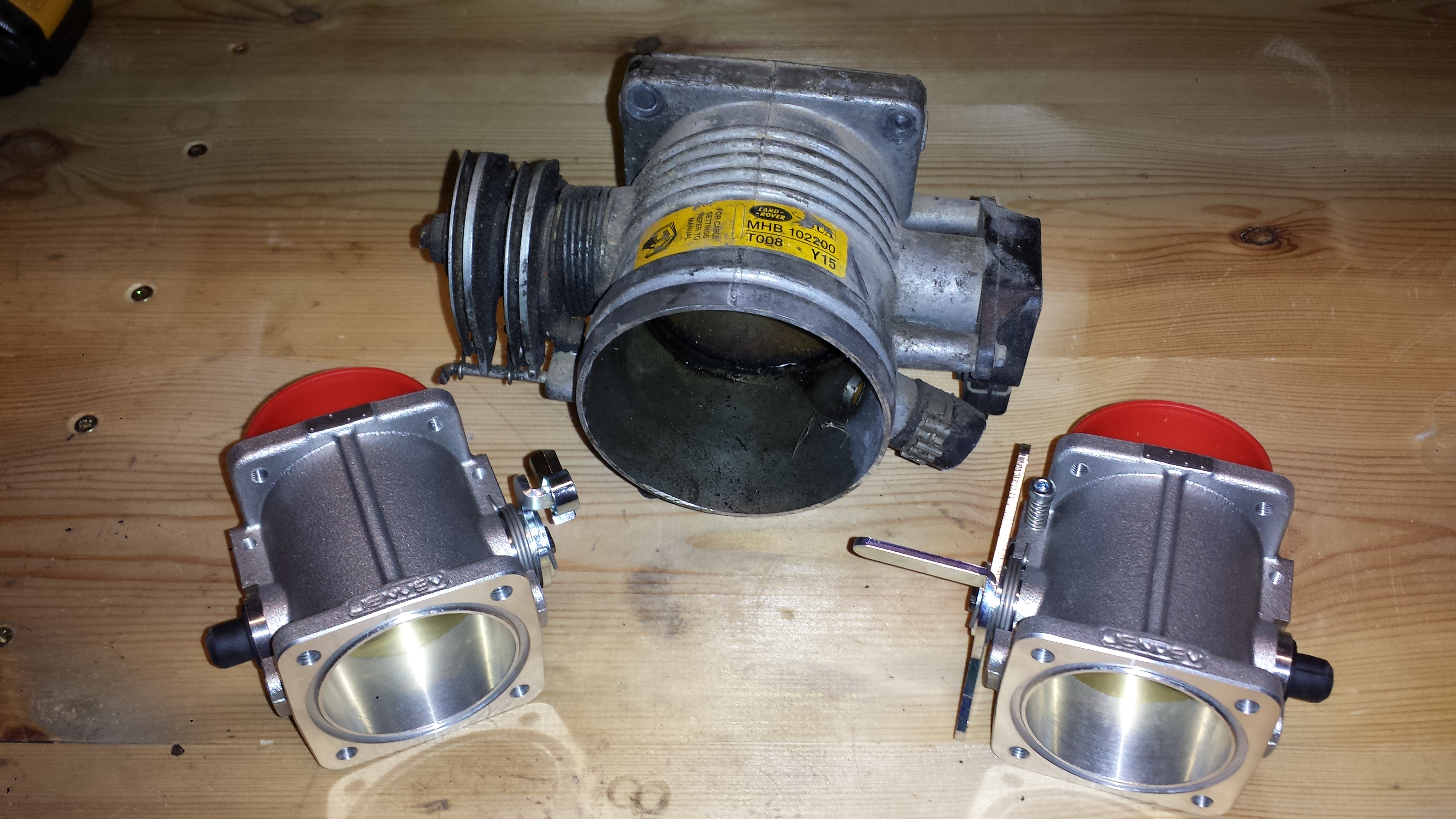
Unfortunately I made an error by severely underestimating the correct throttle size. Now rather than the original 48mm size I will be fitting 60mm or larger Jenvey items.
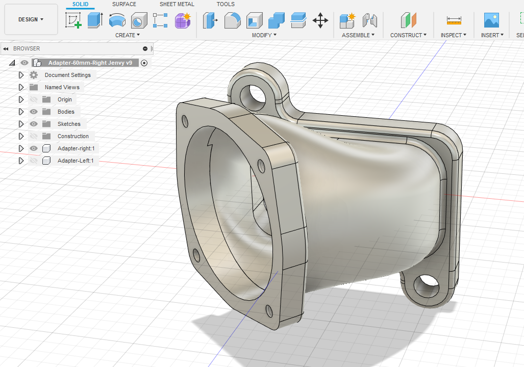
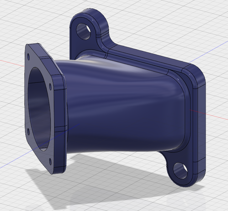
Here’s the revised design in Fusion 360. I will probably have to build in some strengthening webs.
The revised adapter design
These 3D printed items are just for testing, more robust items will be fitted when I’m certain that everything works correctly.
The throttle body size error was noticed by the very helpful Daniel Lloyd from Lloyd Specialist Developments in Warminster. They’ll be setting up the Canems engine management system for me and fine tuning it on their dyno.
That’s all for now. I’ll try to keep these updates more regular while there’s something going on.
Today the Mantula rebuild took a great leap forward as the engine was dispatch for its rebuild. The work will be done by V8 Developments in Lincolnshire. www.v8developments.co.uk
For those who are interested here’s the basic build specification:
4.6 litre top-hat liners
New pistons
New piston rings
New main bearings
New big End bearings
New cam bearings
New core plugs
Fully balanced assembly
Pocketing of pistons
Lapped and polished crank
Special grind short nose Stealth cam kit
Special grind stealth Cam
Timing chain set
High rev Lifters
Running in oil and additive
Comp head gaskets
Comp head bolts
Warrior spec big valve heads
Warrior spec porting
Large valves
New guides
New valve stem seals
New double valve springs
All required gaskets and seals
Fully refurbished rocker assemblies
Recondition and fit front cover, including new oil pump gear and up-rated oil pressure relief valve kit
Fully refurbished rocker covers
Balance front pulley
Lighten, balance, face and machine flywheel to take trigger wheel
Well I’ve been wasting too much time on other important stuff. The Marcos needs some attention. Some important decisions have been made this week.
Chassis modifications
Despite having found a very good welder near to where I live, I have had to look elsewhere. Weld Services no longer answer the phone and are never present at their workshop. That’s a pity because they have done some excellent work in the past.
Amazingly I may have found the perfect alternative. An automotive fabrication/repair workshop only five minutes walk from where I live! I’ve not talked to them yet, but they come very highly recommended. I had no idea that they existed. If they can do the work this will be so convenient.
IRS saga
This really needs a whole post of its own. It’s a tale of frustration at every turn, you just wouldn’t believe how complicated this became and I’ve omitted most of the detail below.
After buying the main IRS and chassis upgrade components from Marcos Heritage Spares nearly two years ago, I found that my fabricated rear uprights would not be strong enough and would also foul the wheel rim unless they were reduced in size and therefore made even weaker. The quote for the real Marcos designed upright from MHS was shockingly expensive, but I had no other option and ordered a set in April this year.
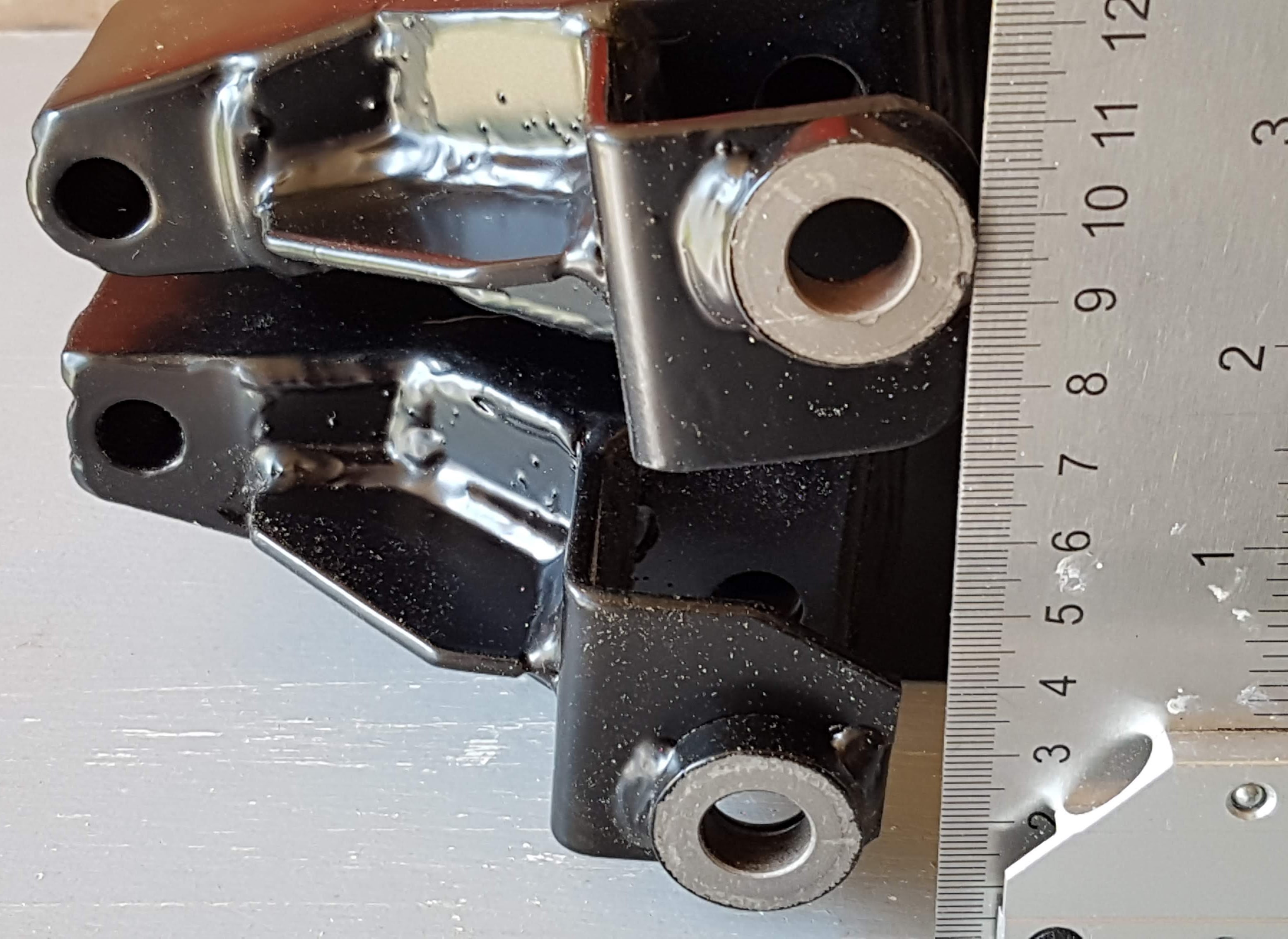
The new uprights arrived about three weeks later and looked lovely at first glance. That was until I examined them more closely and found that the parts were wildly asymmetrical. I was expecting mirrored parts but these were way off.
The shock mounts were in completely different locations;
The top wishbone mounting had insufficient clearance making them impossible to fit;
Worst of all, the hub mounting ring was upside-down on the near-side upright!
I’m pleased to say that the response from Rory at MHS was faultless and he agreed to rectify the parts without any argument. I received the corrected and totally symmetrical parts on 11th June. Now I can finalise the rear end redesign safe in the knowledge that everything is built perfectly. I wonder if any other IRS uprights are as asymmetrical as my original set?
13 mm difference in vertical position.
Engine
I have been toying with the idea of ditching the Rover V8 and moving to a Chevy LS3 crate engine. It’s very tempting and the options list is really suited to my type of project. However it would be expensive and I know of one failed attempt. Reluctantly I’ve had a rare attack of common sense and will stick with the trusty old Range Rover V8. But it won’t be with the slightly tired engine that’s currently sitting in my garage. We can do better than that!
After a lot of research I have chosen a ‘Warrior’ spec 4.6 from V8 Developments. I chose this company for several reasons but mainly because of their flexible and helpful approach to my requirements. They will build an engine to suit the car and the way I want to use it. I’ll give more information in a future update. For now however I have to get hold of, or make a suitable pallet so I can get the engine to Spalding in Lincolnshire.
Back soon, plenty more to tell you as the project comes back to life.
First post of the year and it’s already August! Once again the need to earn a living has prevented me getting much time on the car. Added to that a prolonged attack of gout meant the Marcos had to be neglected. The time I did spend was on the engine, back in February, cleaning and leak investigation.
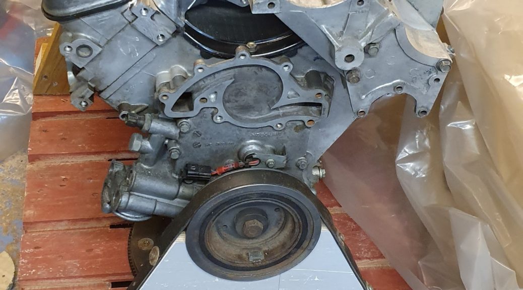
A dirty job
The exterior of the V8 was quite oily, But I think a lot of that is lack of care when filling the oil. Possibly the rear crankshaft oil seal needs replacing as there is evidence of oil in that area too. I spent several hours cleaning it all off so it’s in a much better sate now. I drained the oil and removed the sump too.
The state of the oil rang alarm bells. Yes very black as to be expected but I wasn’t expecting the sticky black sludge at the bottom of the sump. It was still oozing out after 20 minutes looking like something from a cheap 50s horror film!
With the engine on its stand I cleaned it up, but found that it won’t turn-over. It seems to be locked solid, what to do? Maybe this engine wasn’t such a good deal after all…
After that I wasn’t able to do anymore on the car due to a very heavy work load and an inability to walk!
Oilslick
While I recovered I didn’t realise that the bucket containing the old engine oil had a leak, so imagine my delight to be greeted with a shiny black garage floor last week. It took hours to clean up, what a drag…
While I was immobile I did manage to start the design for the chassis modifications. More on that next time.
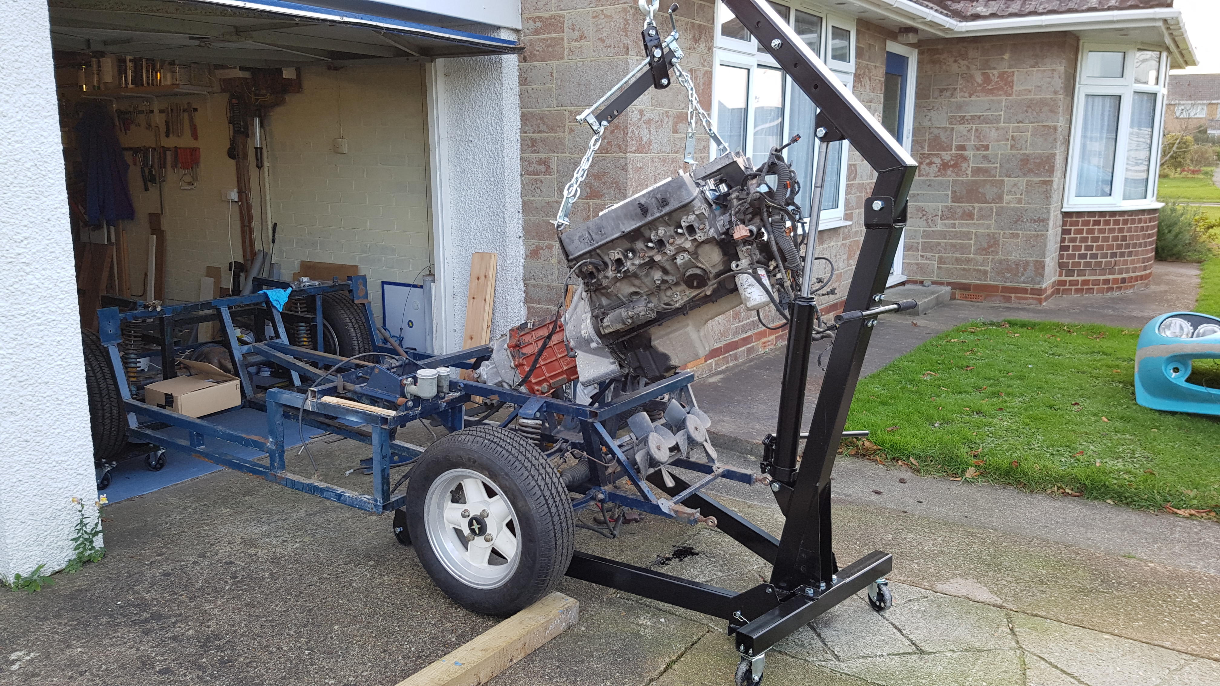
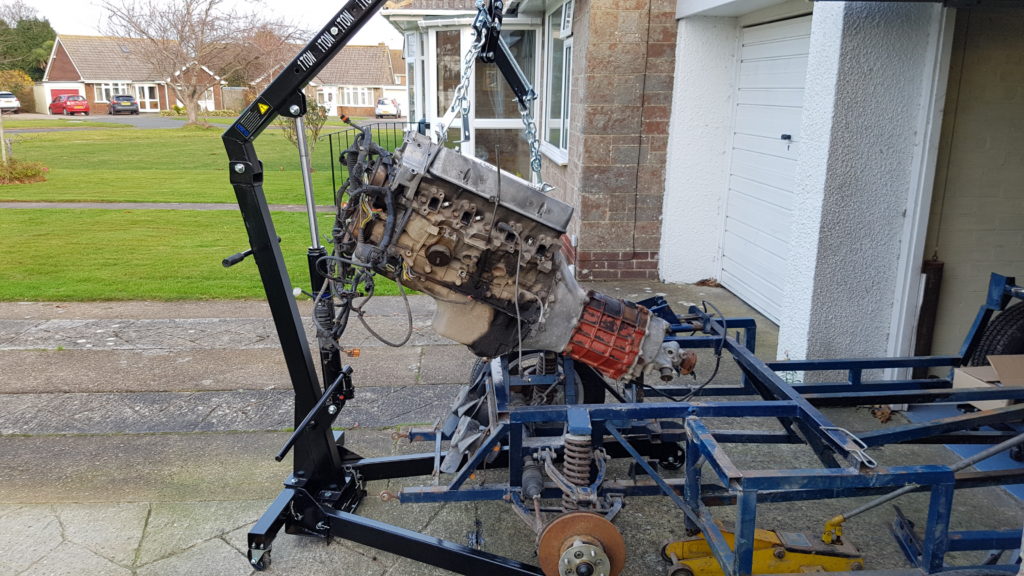
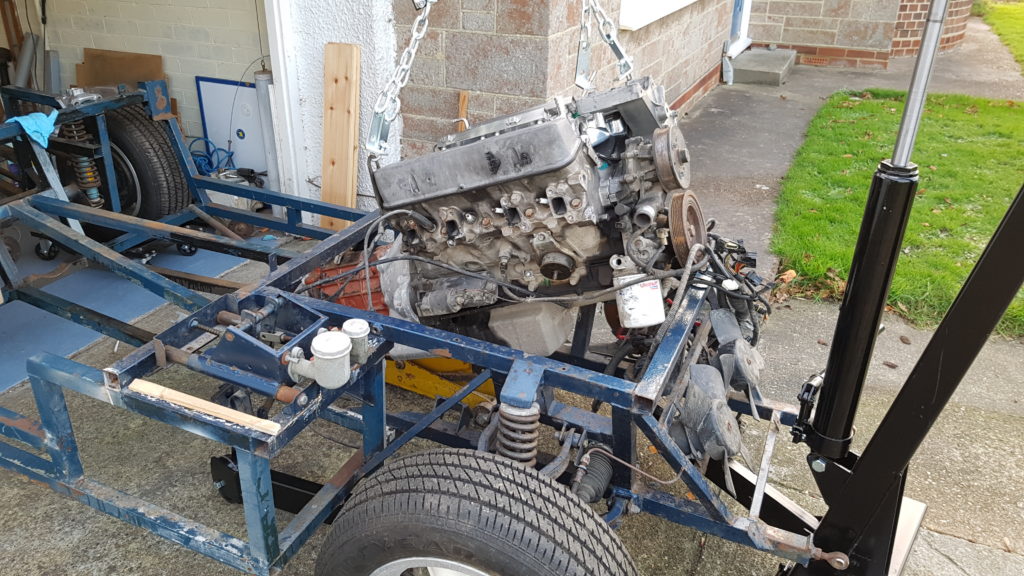
A long day on the Mantula yesterday. Engine out and on its stand ready for cleaning, painting and modification.
I was using the new Engine Crane which I bought from SGS Engineering. In the past I’ve hired engine cranes, but this is more convenient as it was available while I waited for a dry day.
The load lever makes it so much easier to set the engine at the best angle to clear the chassis rails, recommended.
Engine Stand
Mounting the engine on the stand was the easy part. Unfortunately I discovered a broken bell-housing bolt. No problem I thought just use an ‘easy-out’ or stud extractor. So, centre punch the broken bolt head, drill out the centre and insert the extractor. Wind it in counterclockwise then watch in horror as it breaks off! Leaving a useless piece of hardened steel stuck in the engine block.
It’s always a pleasure to support a real craftsman. Someone who always puts all of their expertise into their work. Peter Mulberry of Mulfab is one of those people. I found his company while looking for ideas for a new fuel tank on the internet. The pictures on the Mulfab website are really worth looking at.
The reason for changing the sump is that the Range Rover V8 uses an extra deep cast aluminium item. This is so deep that the static ground clearance is about 50 mm. It wouldn’t survive the first test drive! I needed a suitable replacement and I couldn’t use any old Rover V8 sump because my engine has the crank-driven oil pump and therefore a different flange shape at the front.
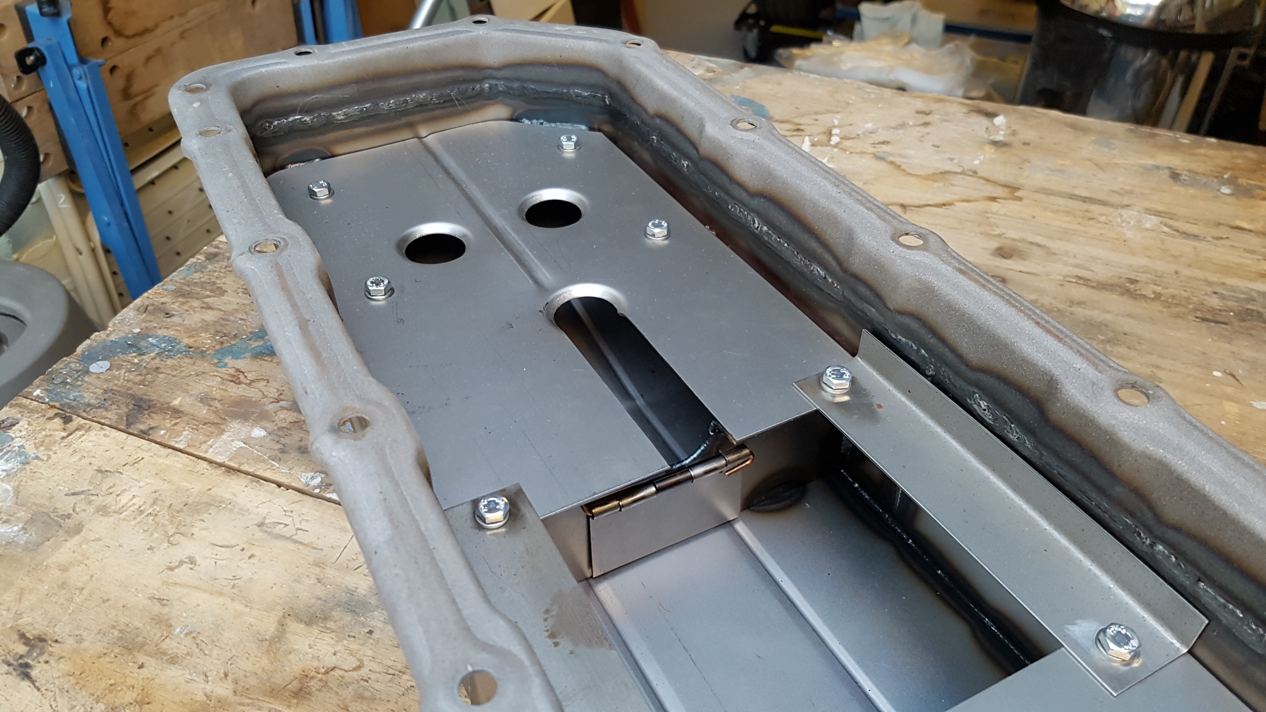
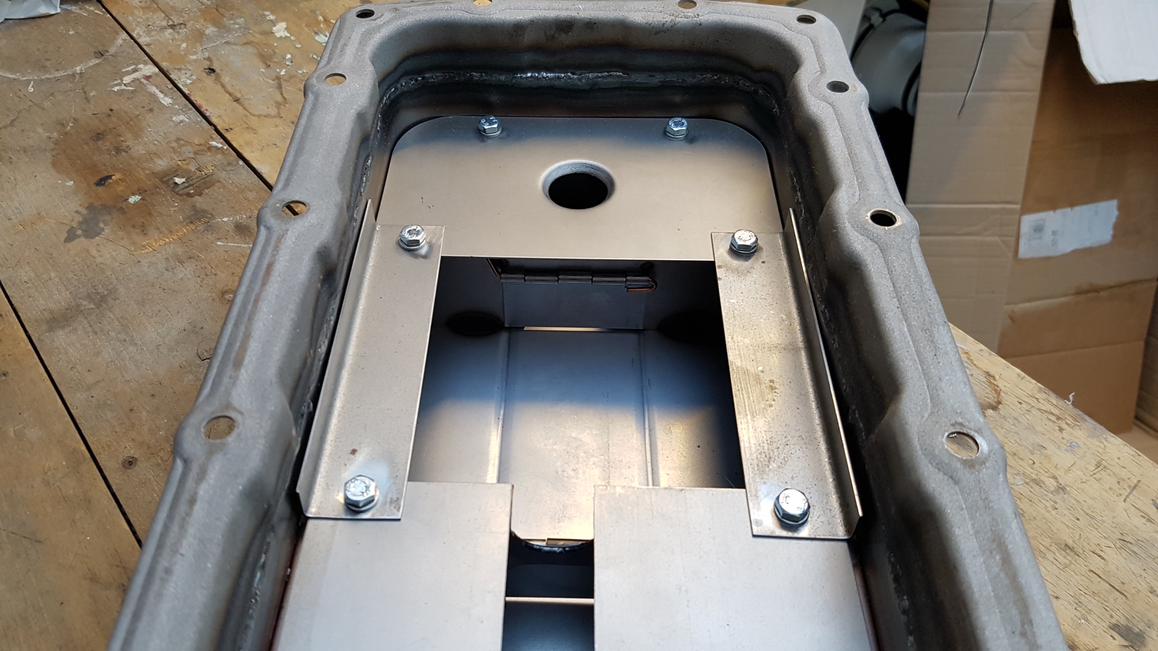
Here it is, made to my requirements, but designed entirely by Peter. I simply told him that when installed it should project no lower than the bottom of the bell housing. He did the rest. It includes two hinged flaps to prevent oil surge which could be a problem with a full length design. Not cheap, but worth every penny. Let’s hope it will survive the Isle of Wight’s bumpy roads…
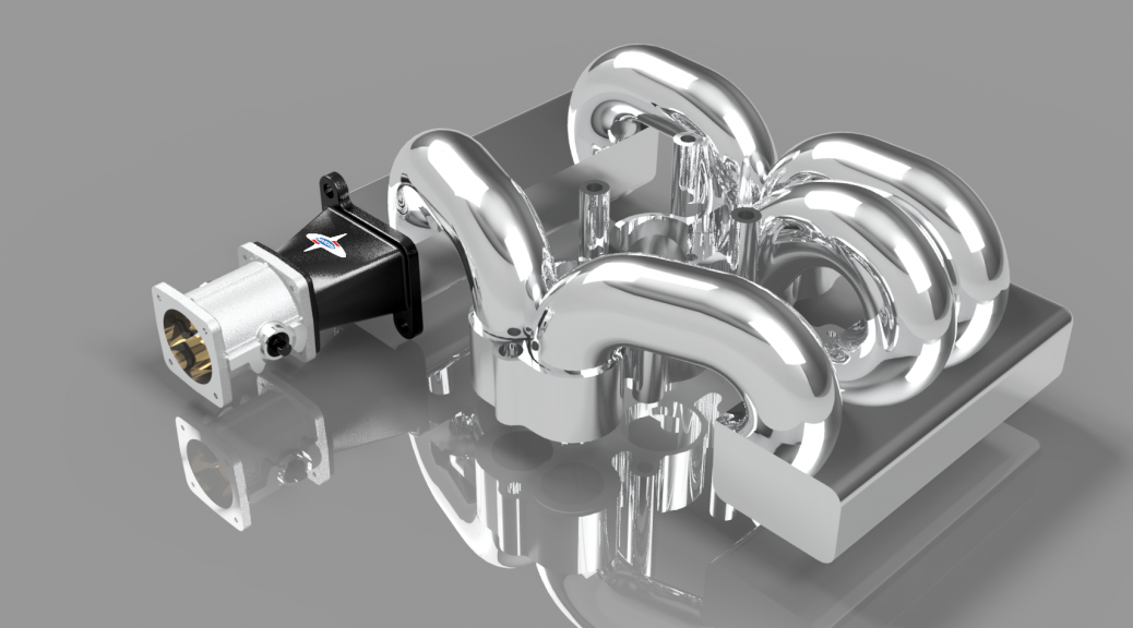
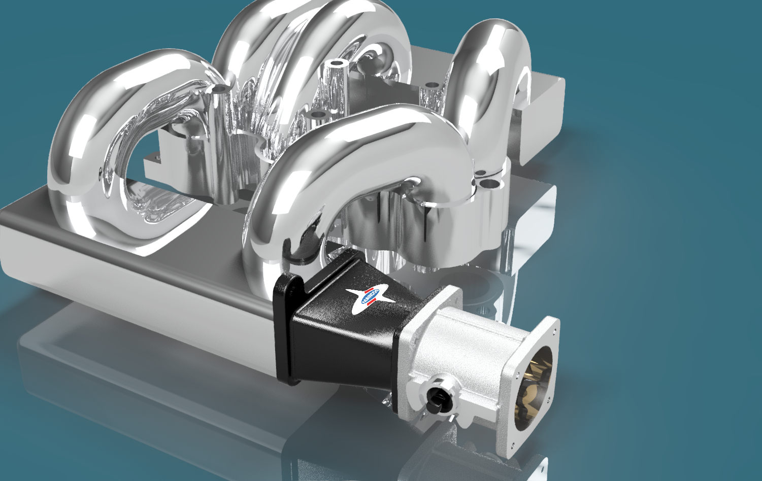
Today I collected the results of my experiment with 3D printed parts. In a previous post I showed how I was designing a revised inlet system using two new throttle bodies to replace the standard Range Rover part. The design has matured a little and the geometry is now fixed so it would be great to get the parts manufactured.
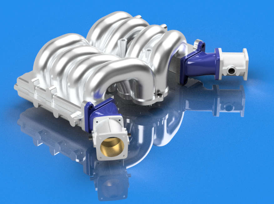
The final adapter design in Fusion 360
This is a screen capture from the Fusion 360 CAD program showing the adapters in place on the manifold.
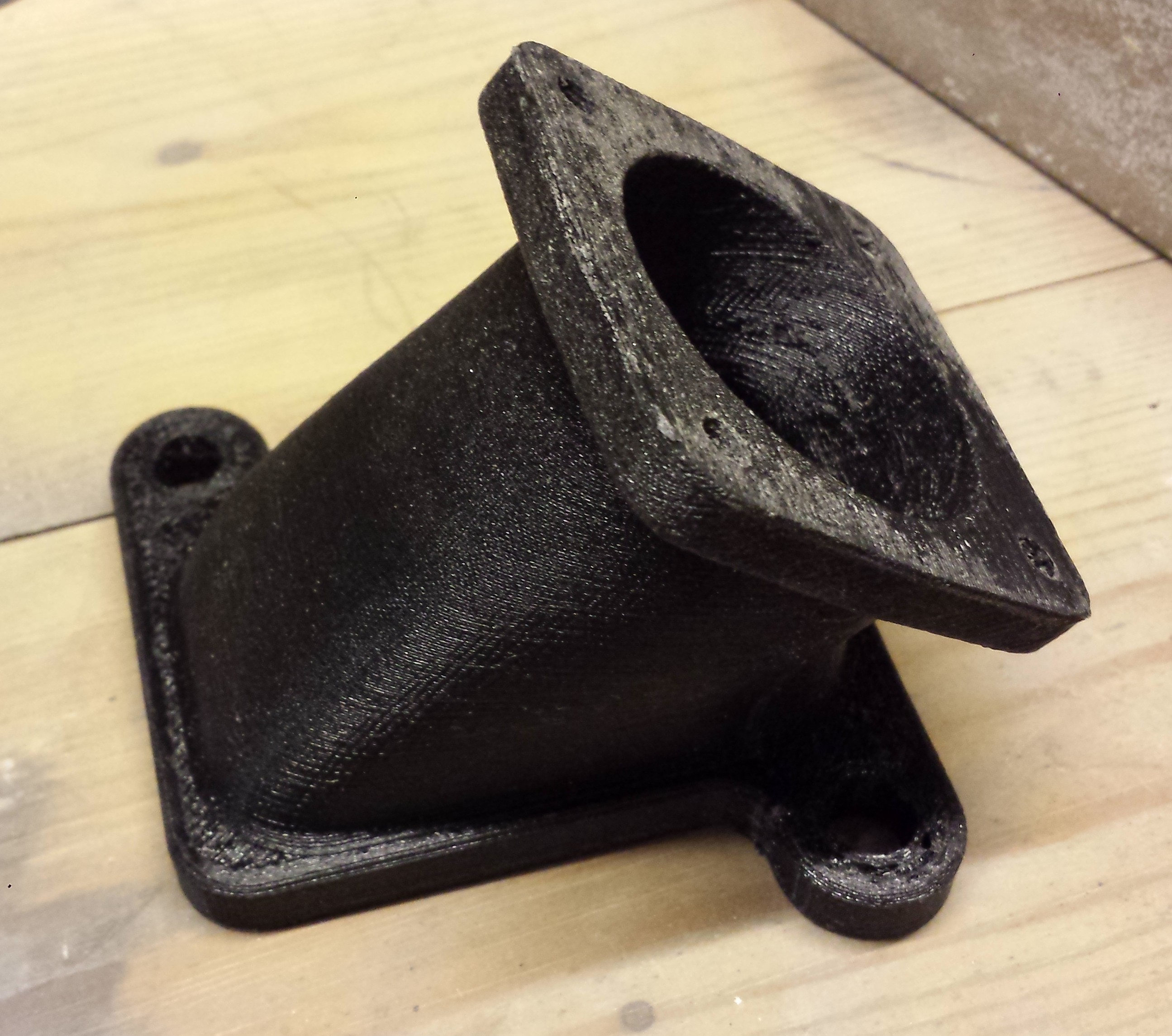
This is the result, printed here on the Isle of Wight by Island 3D Printing.
And here’s one of the adapters with a throttle body attached. The oil filler tube will have to be relocated before I can mount the other side.
Sorry that I’ve been so quiet for the last couple of months. Progress on the car has been minimal due to other commitments. While I’m out of the country often it been impossible to get anything done.
I’m sure you would prefer to see pictures of the Mantula, but nothing new to show yet. However time hasn’t been totally wasted as I prepare to design the changes for the inlet system.
Fusion 360
The image below shows the work-in-progress on two fronts. The first front is learning to use a 3D parametric CAD system. I chose Autodesk’s Fusion 360 Ultimate. It’s really easy to learn, has an appropriate feature set and is affordable. For any ‘hobbyist’ it is free, at least for now… Better even than that it’s a joy to use. I think I’m becoming addicted.
Second front is the design of the inlet system.
The model still has a long way to go, but I think it’s worth the effort. Drawing the plenum has been a real challenge due to its totally asymmetric, organic design and overall complexity. As you can see I still have three more inlet runners to model, plus all of the fixing points.
The next part is the black mounting adapter with the Marcos logo. This will be 3D printed once the final design has been fixed. The current version needs some rework for clearance. Of course I will only know the effect on performance once I get to run the engine.
The last part shows one of the Jenvey 48mm throttle bodies. This has been modelled to 0.01 mm accuracy to ensure that the throttle linkage works first time. A really great feature of Fusion 360 is the ability to design joints that are limited to a realistic range of movement. So far I have the throttle opening the correct 83 degrees. This will be eventually joined to the main link mechanism, again with accurate movement limits.
For the next few weeks I will be completing this design work. Then I’ll send the CAD files to a local machine shop for manufacture.
Jenvey throttle bodies
As mentioned above I’m going to use the excellent Jenvey throttle bodies to replace the original Range Rover item. Here’s a comparison.
Two smaller throttles should give better response than a single large throttle. I can’t wait to find out!
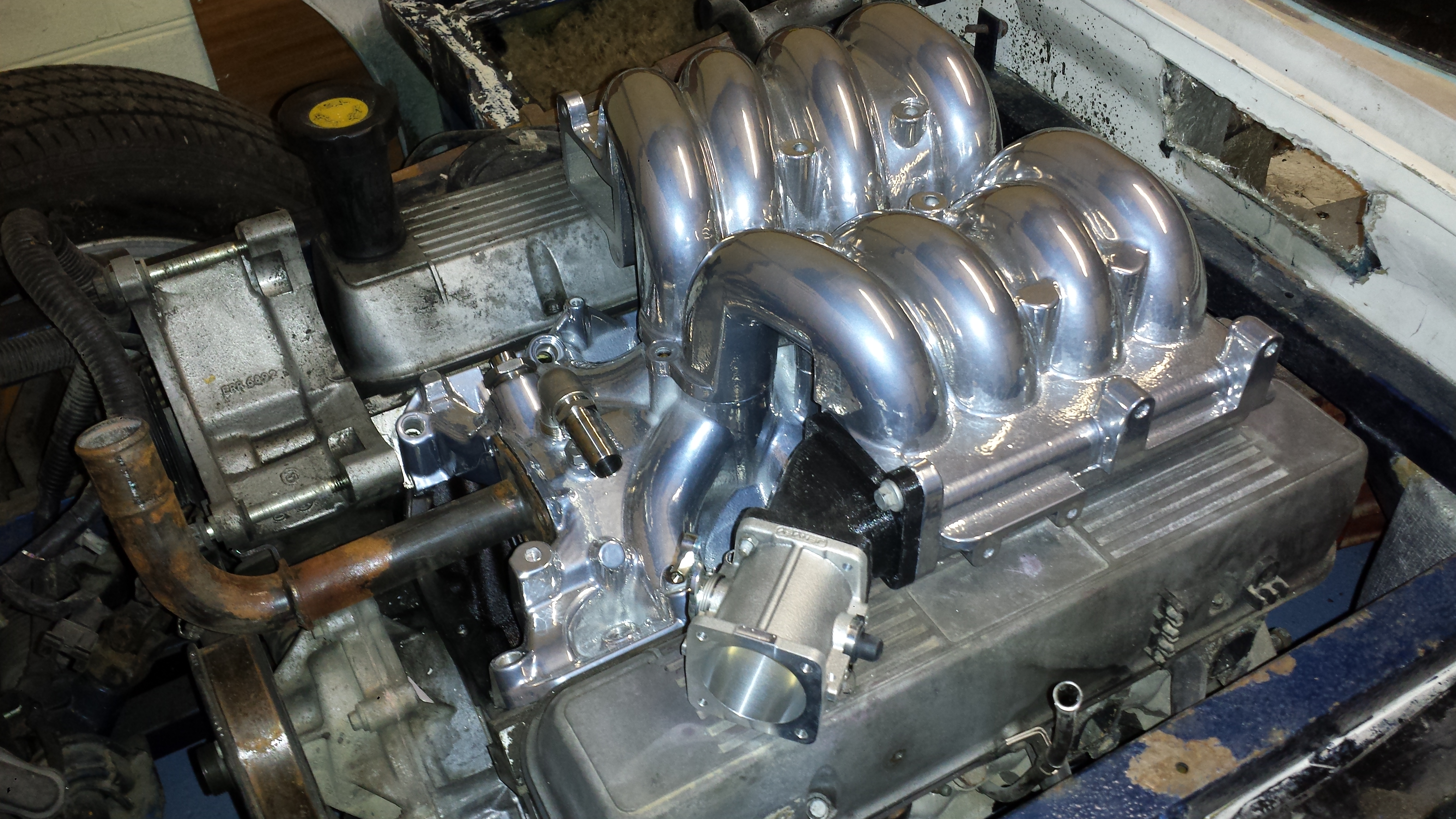
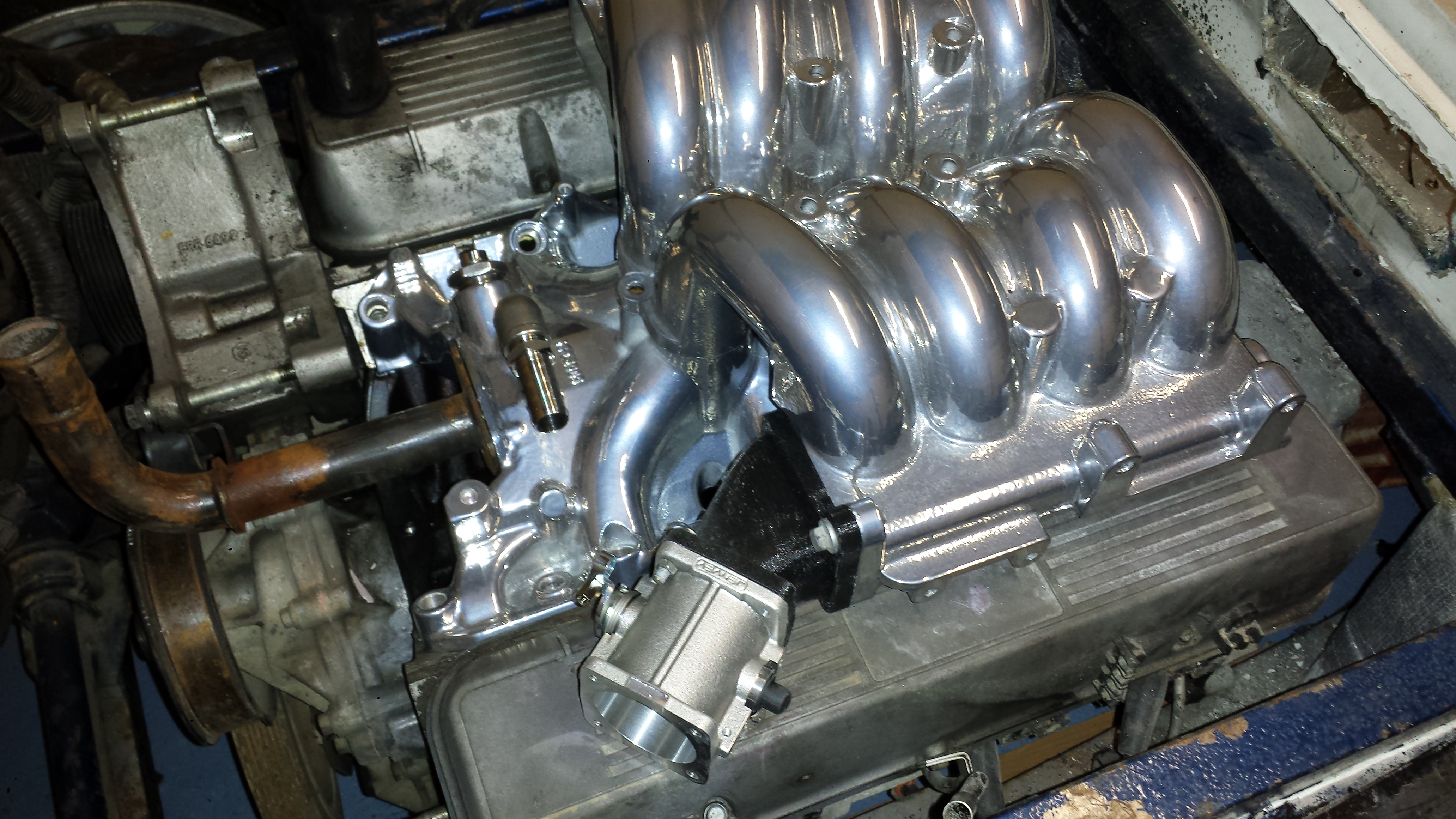
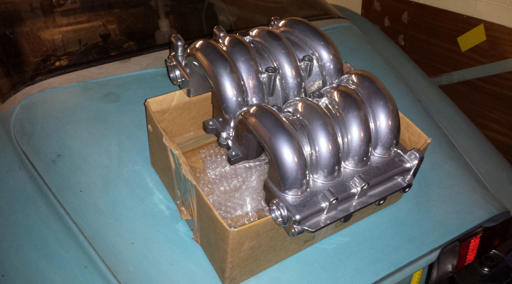
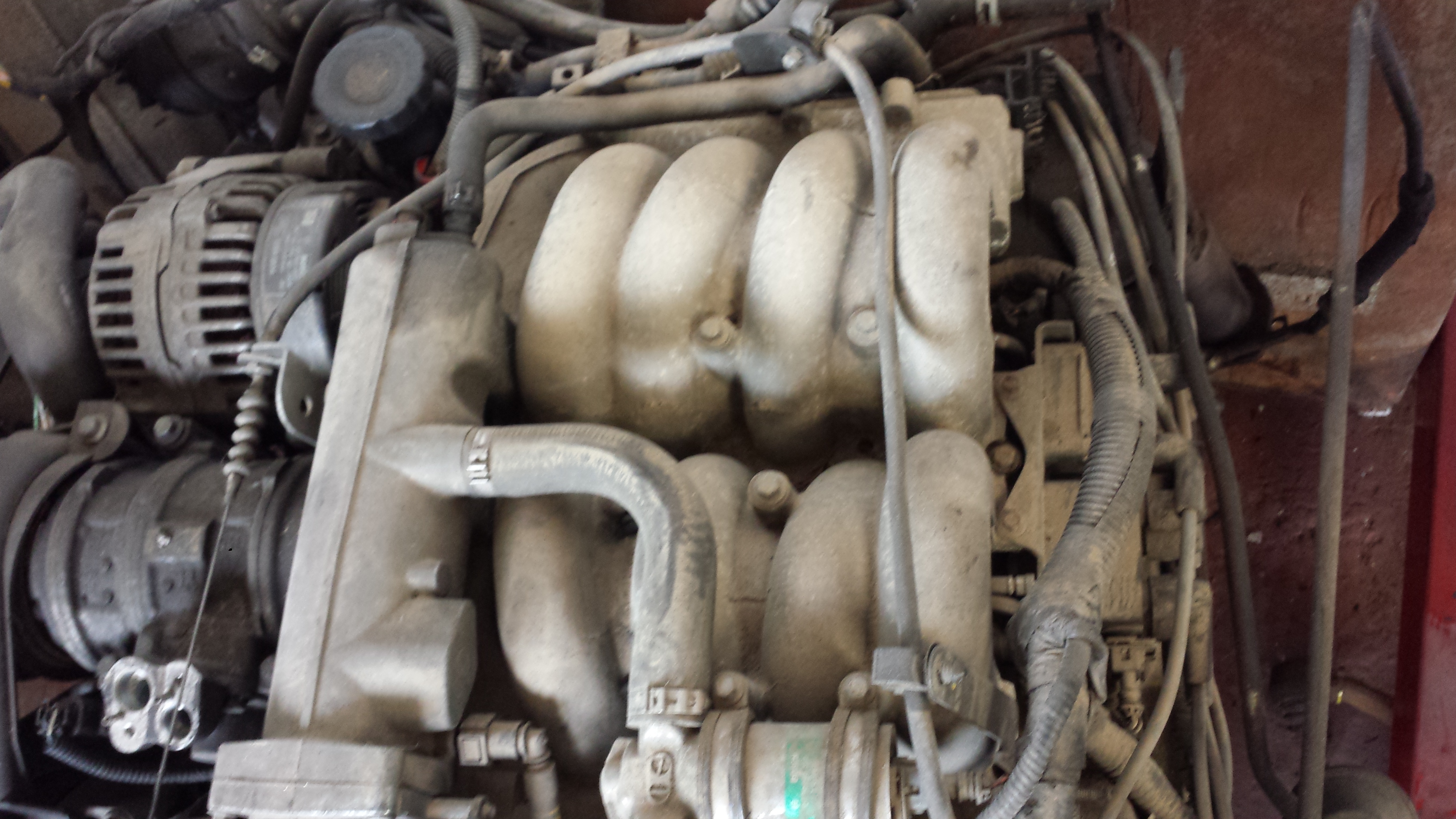
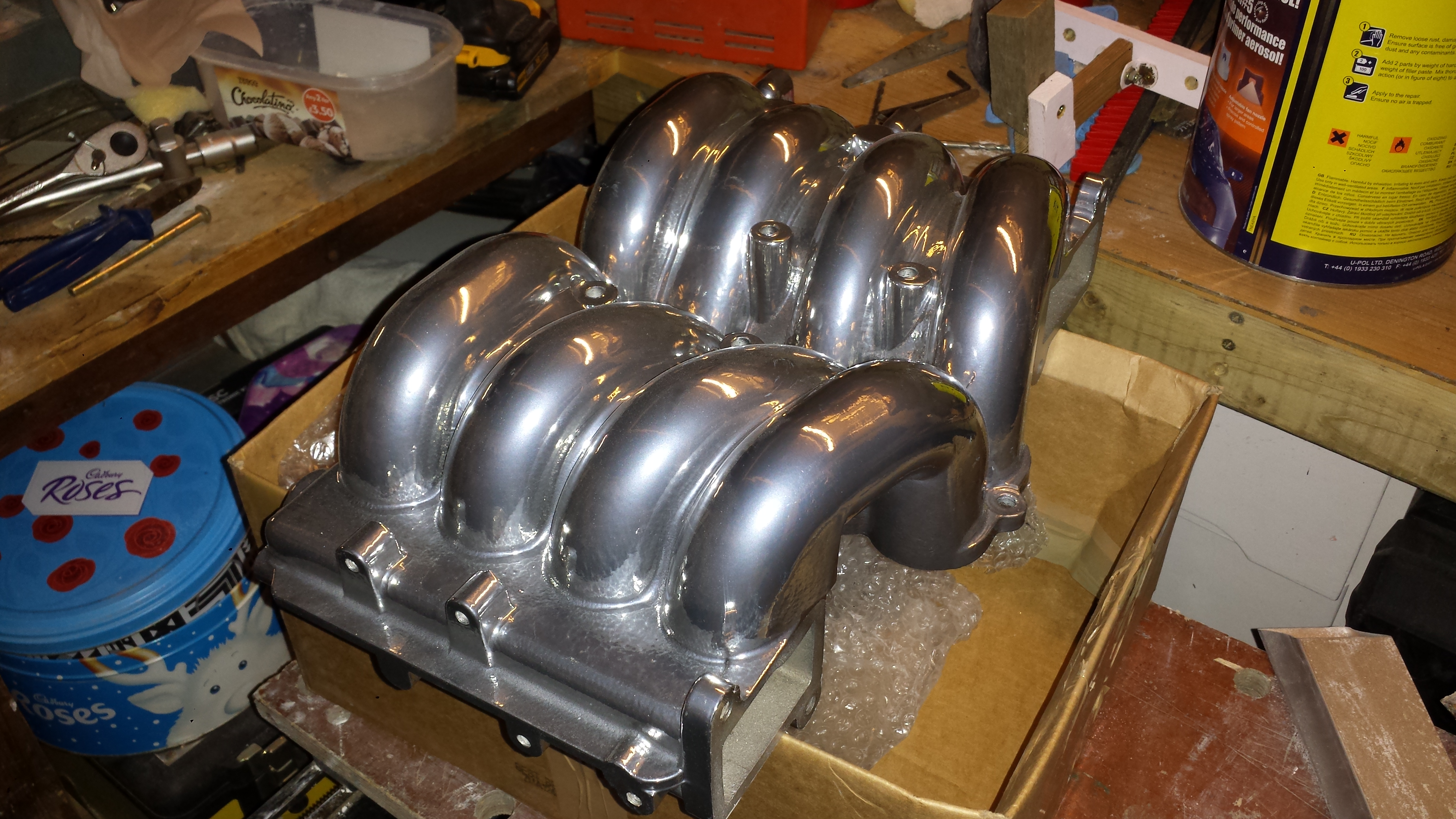
Sometimes it’s nice to see a part of the car looking good even when everything else still looks rough. That was the reason for getting the top half of the inlet manifold powder coated in chrome effect.
Before and after…
I think it looks pretty good, so thanks to Bret at Vectis Powder Coating for a job well done.
The lower half of the manifold is being machined by SeaTek Engineering in Cowes. This will re-align the water outlet to take a more direct route to the heater matrix.