MDF, foam and filler – part 1

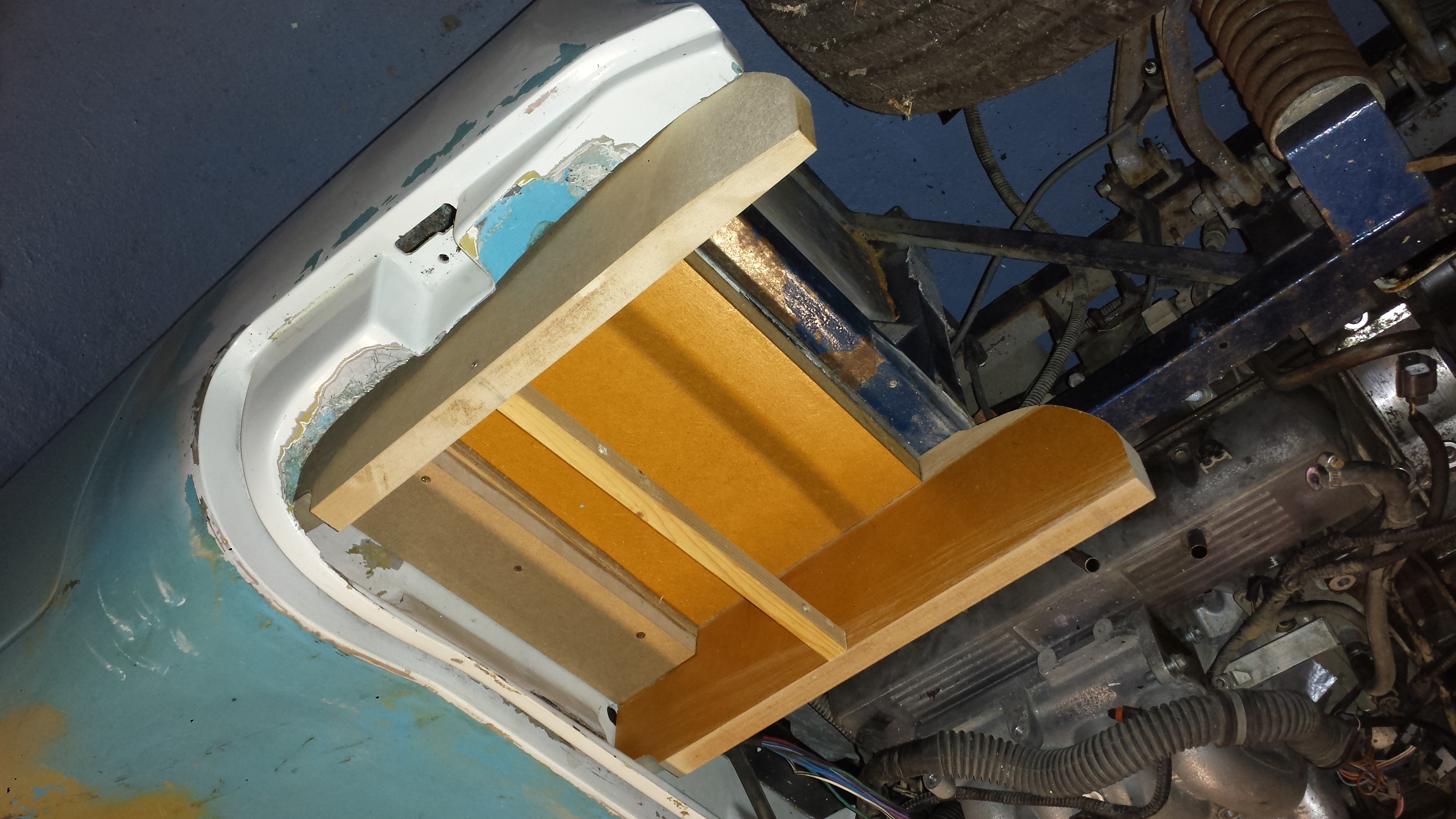
I’ve started making the pattern for the air conditioning housing. It a box made of 25mm  MDF that is built in position on the car. It probably didn’t need to be that thick as it makes for a very heavy construction, but it’s solid and should remain in shape as its gets worked into its final form. It also has the advantage of allowing deep features to be carved into the surface.

While the base of the box has to fit to the chassis steelwork, the upper section can be more stylish. Of course it needs to fit under the bonnet, but that should help to define the general shape.

At the front of the box the idea was to give it the rounded profile similar to the a Marcos pedal box. With that in mind I transferred the curve from the inner wing onto the box side. I adjusted this to be little more uniform and to give some clearance. Then I transferred the same curve to the outside. With both parts cut it I assembled the box. So far it’s all looking good.

Sides and base connected

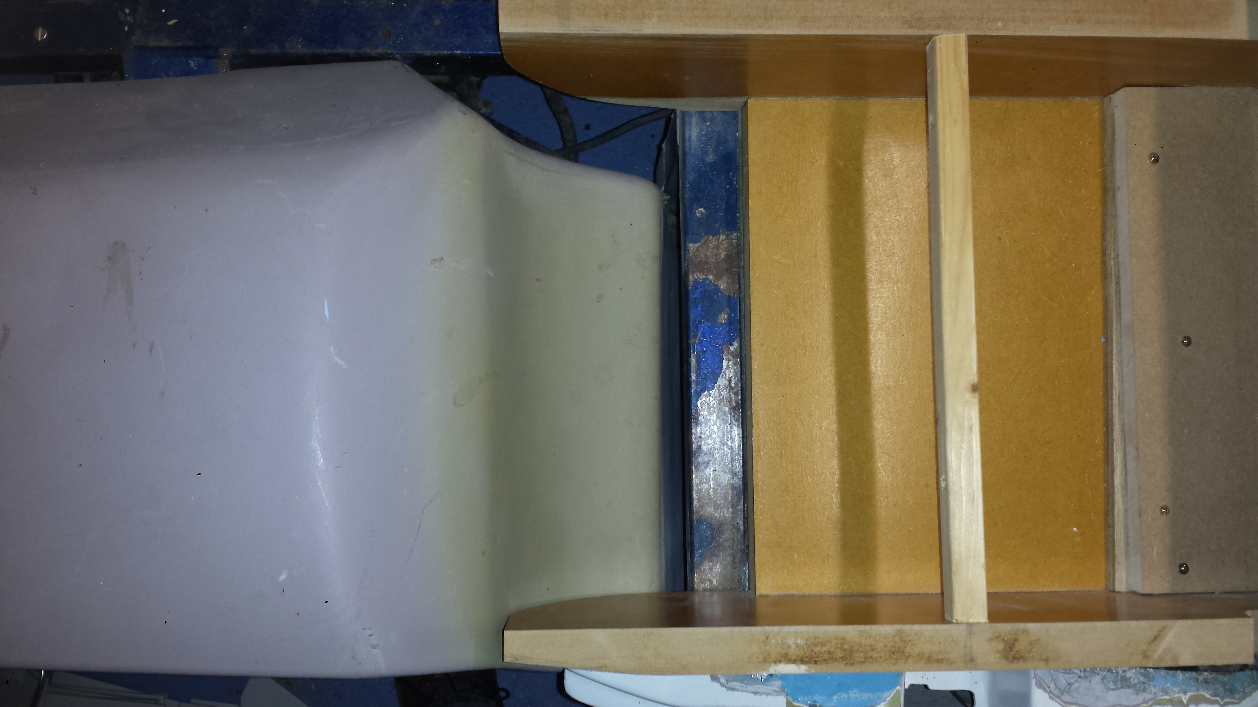
That will never fit…

Once again the “informal” Marcos approach to mould making has caught me out. The inner wing profile is all over the place. The curve fits on the inside edge but is a least 20 mm out on the outside. That means the inner wing does not fit. In the picture below you can see the gap between the inner wing and the chassis.

Outer edge pushes the inner wing forwards by 20 mm

How do I handle this? Well there are three options:

  1. Trim the outside profile by 20mm to make it fit the existing inner wing. The would make the a/c box asymmetric, but would fit any Marcos Mantula.
  2. Trim both profiles to make it fit and symmetrical. This may emphasise the asymmetry of the inner wing, but would also fit other installations. Space for the blower would be compromised.
  3. Re-design the inner wing. I was going to have to do a lot of work in this area anyway. The original wings are a very poor fit in any case.

In the the end it was an easy choice I’m going with option 3. This also has the benefit of giving the blower enough room for optimum airflow.

More in the next exciting instalment…

Systems design

Progress has been very slow over the past few weeks. Travelling away for work most weeks in Paris and talking at a conference in Bristol means that come the weekends when I’ve finished the backlog of DIY jobs there’s very little time left for the Mantula.  🙁

However there’s always a chance to do something. When I’m away from home I can design the systems layout and do a fair amount of research too.

There is an immense urge to strip the whole car down and get the really exciting big jobs done. IRS conversion for example. But I’m forcing myself to take it slowly and plan everything properly now while I can. You see, the old Rover 3.5 V8 installation was quite simple; no oil cooler, a/c or fuel injection.

The really complex part now is the routeing of all of the pipework, ducting and wiring loom branches. To say that the original Range Rover engine installation is busy is a major understatement. I will have to find alternative or modified locations for all of this:

  • Plumbing for the oil cooler,
  • Plumbing for the air-conditioning,
  • Plumbing for the engine coolant system,
  • Throttle linkages to the new Jenvey throttle bodies.
  • Twin ducts for the engine air intakes,
  • Single, large-bore air intake  for the air-conditioning,
  • New engine wiring loom,
  • New engine management system,
  • New dual-circuit brake, clutch and throttle layout along with a new pedal carriage and pedal box/housing.

What should I do first?

For one very simple reason I’ve chosen the air-conditioning system as my first real design task. The reason? Well, it’s the only part of the engine bay that’s easy to work on right now! But it’s also a real challenge too. I want to prove that it is possible to fit a really worthwhile climate control system in a Marcos.

Most of the design effort will go into the air-con housing that will sit over the passenger foot well. This will contain the blower fan, evaporator and heater matrix. There will also be servo controlled flaps for hot/cold air blend and fresh/recycled air.

I will be following conventional a/c system configuration where all of the incoming fresh or recycled air will pass through the evaporator. This gives the benefit of working as a dehumidifier even if the air has to also pass through heater.

So far I have the blower with the evaporator due to arrive tomorrow. Both parts have been supplied by Adam at T7 Designs – excellent service  and a pleasure to do business with.

For the a/c housing box I will be trying something new, at least for me. It’s going to be a carbon fibre part using resin infusion. If you haven’t seen this process yet here’s a video by the helpful people at Easy Composites…

Before I can get there of course, I need to create a mould and before that a ‘plug’. I’ll post some pictures of my progress as I go. So far I have just cut out one side of the box from MDF. The top of the plug box will be built up from expanded foam so that it conforms to the inside shape of the bonnet. This will be smoothed out using polyester filler to give the final shape. After that it needs a perfect glossy finish which is built up using Pattern Coat Primer followed by Pattern-Coat Hi Gloss finish.

After that I will create the three part mould (another long process). Finally I can create the actual part in beautiful carbon fibre. A lot of work for a simple box, sure, but, if it all works well maybe I’ll put it into production.

Other parts on my Carbon Fibre list are:

  • Pedal Box,
  • Inner front wings,
  • Inlet manifolds,
  • Fresh air inlet duct,
  • Parts of the new dashboard,
  • Battery box
  • Bonnet hinge/support structure (you wouldn’t believe how rough this is, a real botched job on my car).