OK, I should have written this up months ago, but my time is not my own these days. Despite lock-down my job has kept me very busy. I already work from home, so it’s been no real change for me. Only the occasional hour to work on the Mantula.
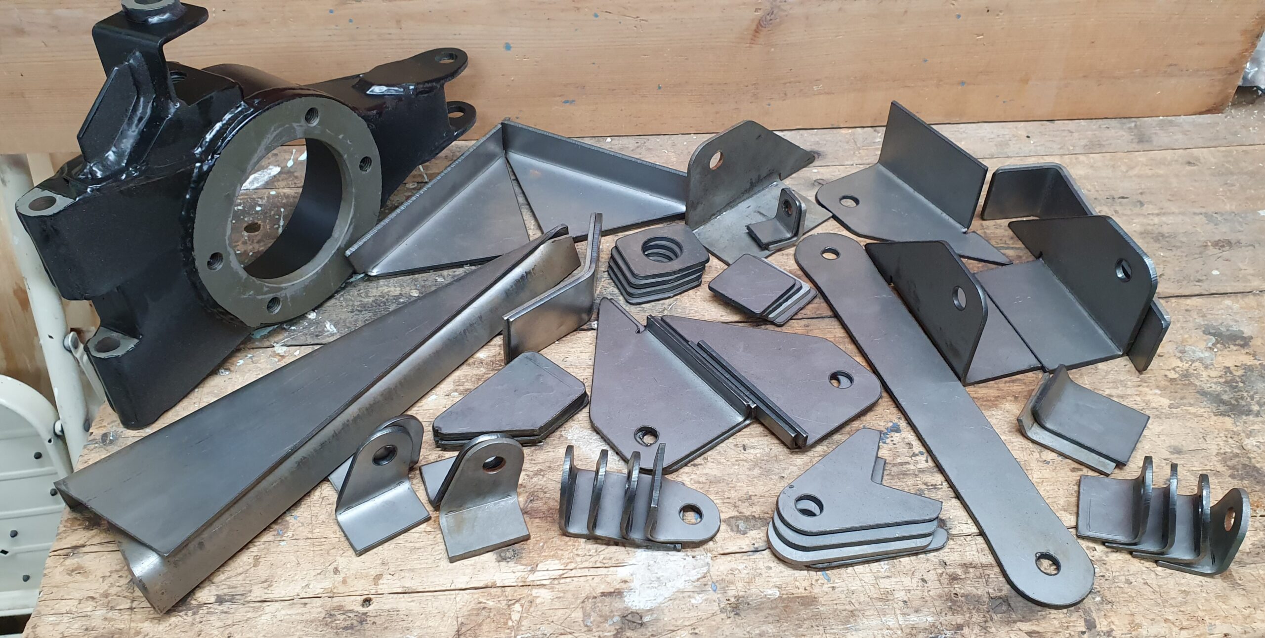
Back before the lock-down came into effect I was able to get the chassis over to George at Arch’s Speed Shop here in Bembridge. It was his job to make sense of my design and the 57 plasma-cut pieces that would eventually become the new IRS chassis update.
Plasma cut parts
The chassis modifications were drawn in a 3D CAD programme, the excellent and versatile Fusion 360. I really enjoy using it and it’s free for hobbyist users.
The process of designing the CAD model is my preferred way to ensure that the job is right first time. I can design everything to the fraction of a millimetre and see the problems before any metal is cut. Perhaps if I had the fabrication skills I would make it up on the car. Maybe for my next build…
Fusion 360 has a sheet metal design mode and I used that to work out the correct bends and then export the DXF files that are eventually loaded onto a CNC plasma cutter and cut out of 3mm steel.
That plasma cutter is owned by Ray at Northshore Classics and he did a great job for me including the folding according to my drawings. I was very pleased with the quality. He’ll be doing more work for me as the build progresses.
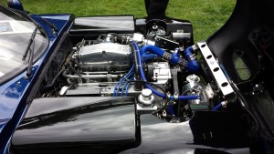
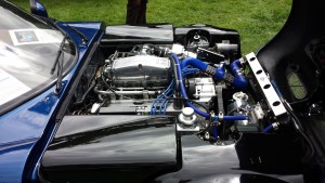
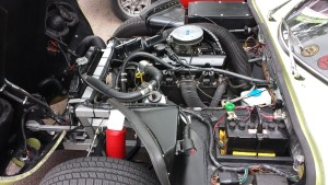
Arch’s Speed Shop
I was very lucky to get the chassis conversion done before lock-down, but it was close. The chassis was collected on 9th March and returned on Friday 20th March. Lock-down started on the following Monday.
I sourced the steel tube which was a perfect match to the original 1 1/2″ x 14 swg. Mine was supplied by Metal Supermarkets.
These parts were supplied by Marcos Heritage Spares as part of the seat belt mounting upgrade kit.
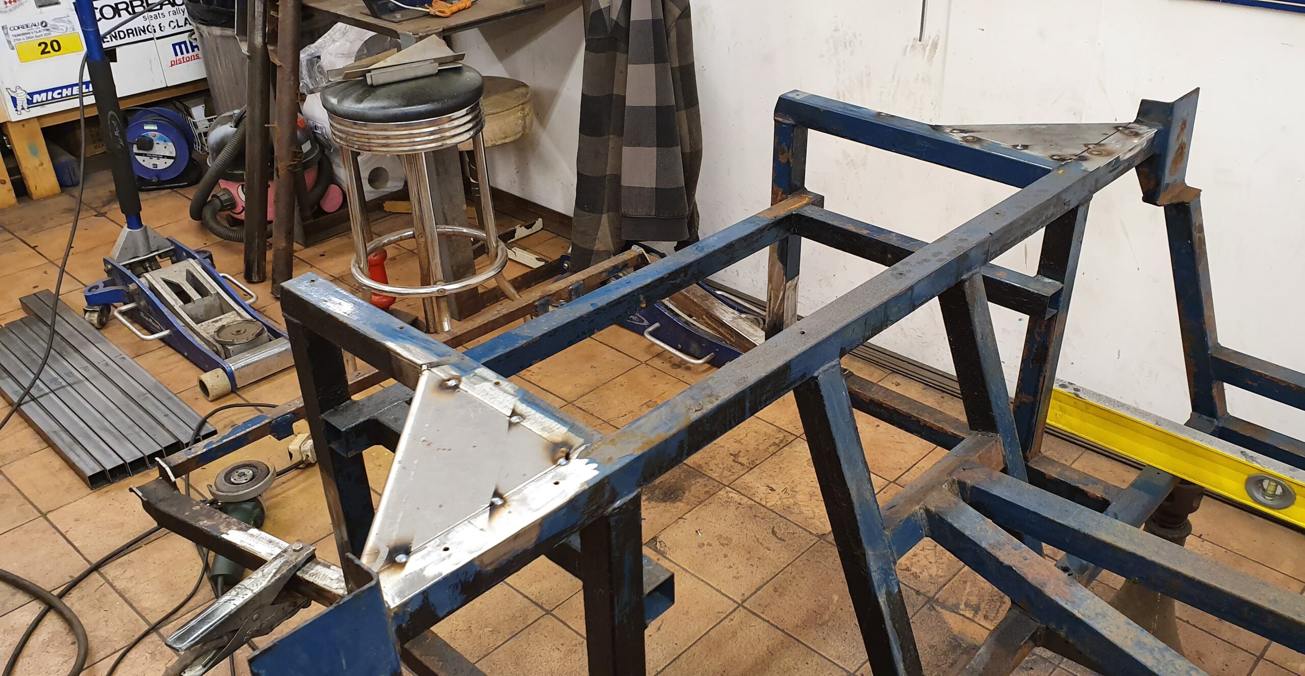
Rather than remove the existing door striker plates we decided to double-up. The plates were spot welded together then welded all-round to avoid water penetration. This adds a little more stiffness in this relatively flexible area. It also ensures that the body will still fit.
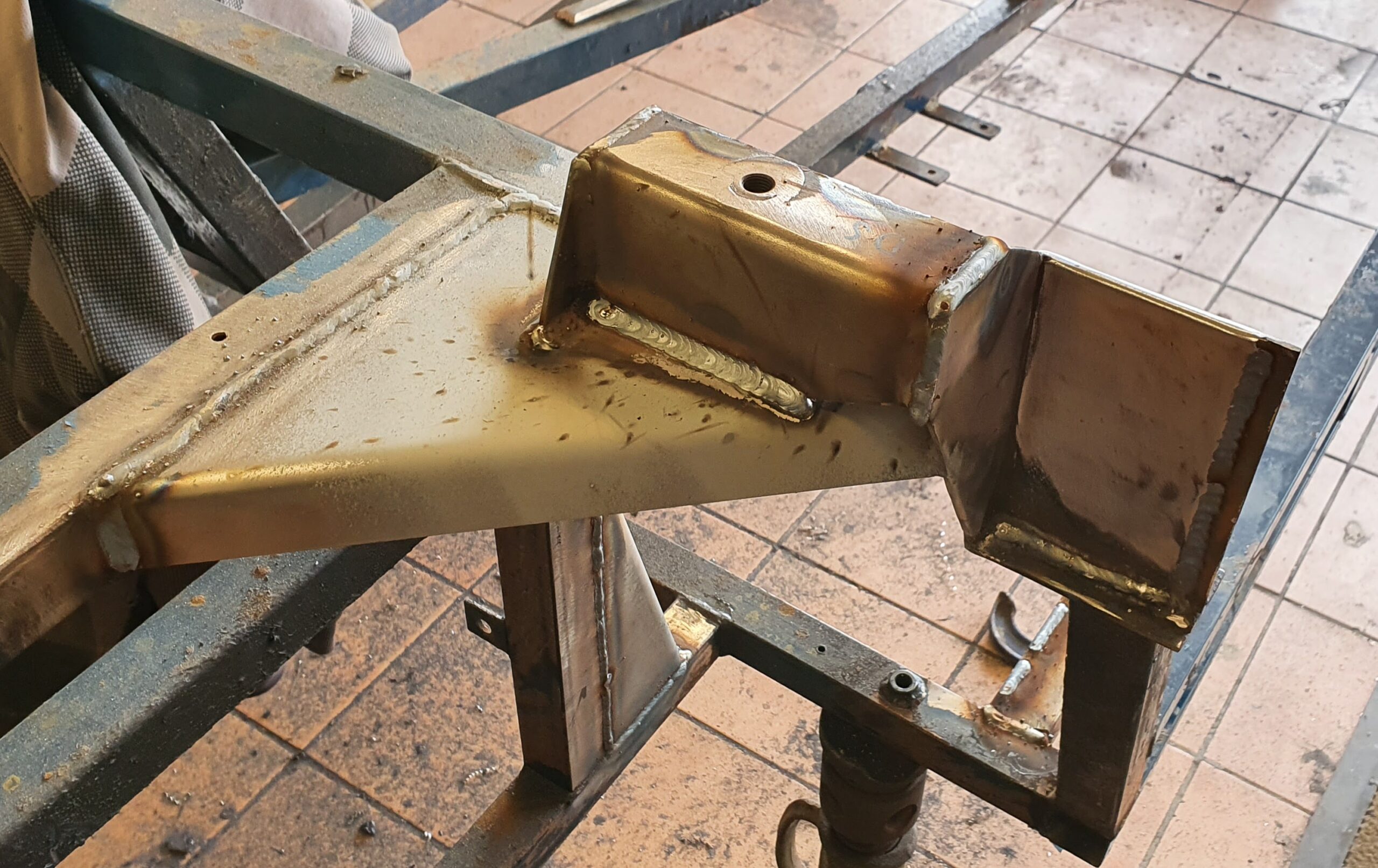
Rear view of the seat belt mounting. As this area is open to any road debris thrown-up by the rear wheel it was later decided to fill any potential water traps. The welds were rather spattery probably due to contamination. Maybe not the prettiest welds but we have very good weld penetration – this isn’t going to fail!
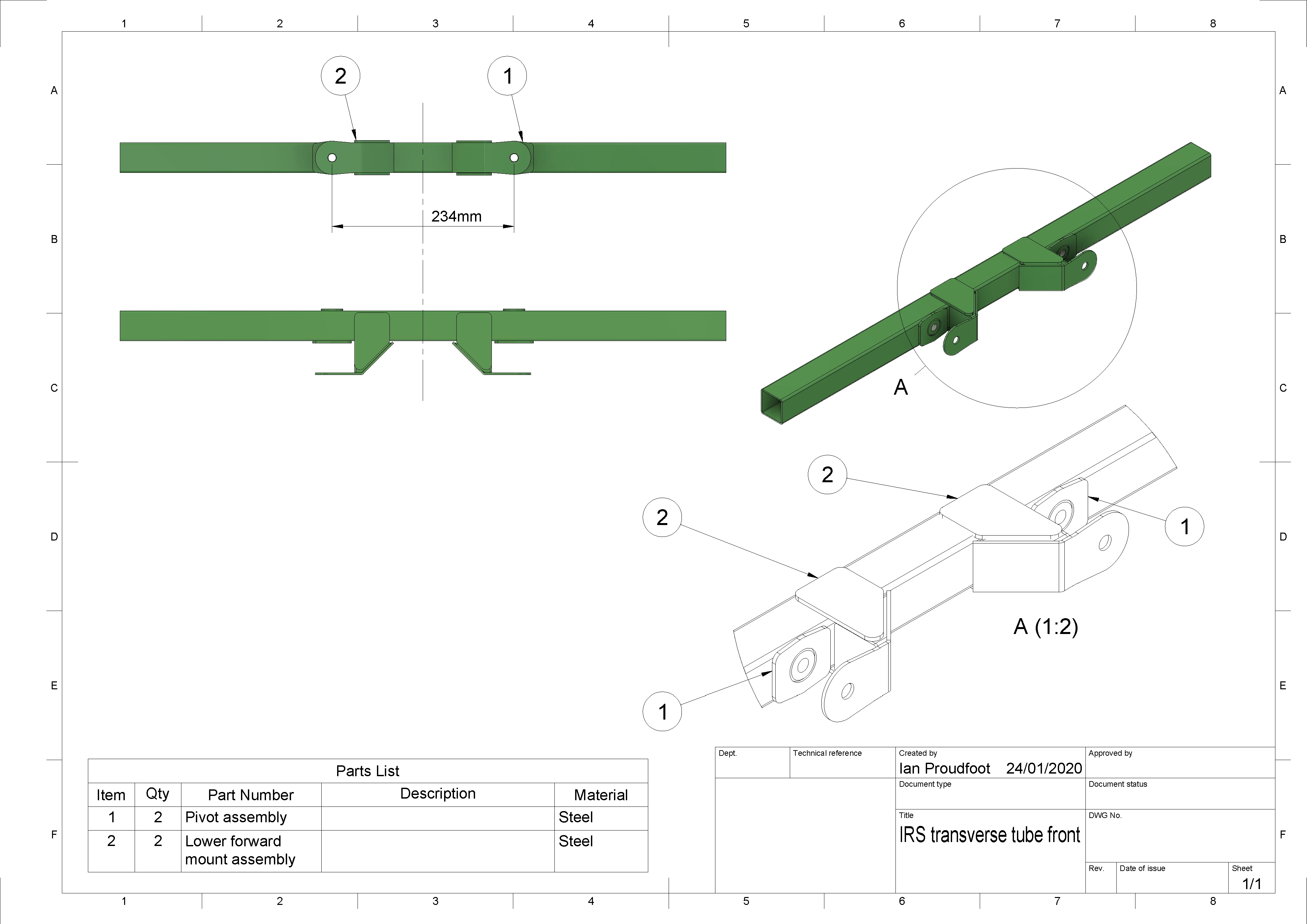
It’s easy to create working drawings from the 3D model in Fusion 360.
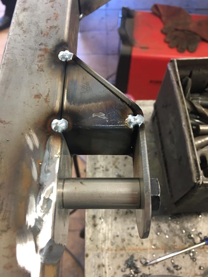
This is about to be welded-up then top and bottom fish-plates added.
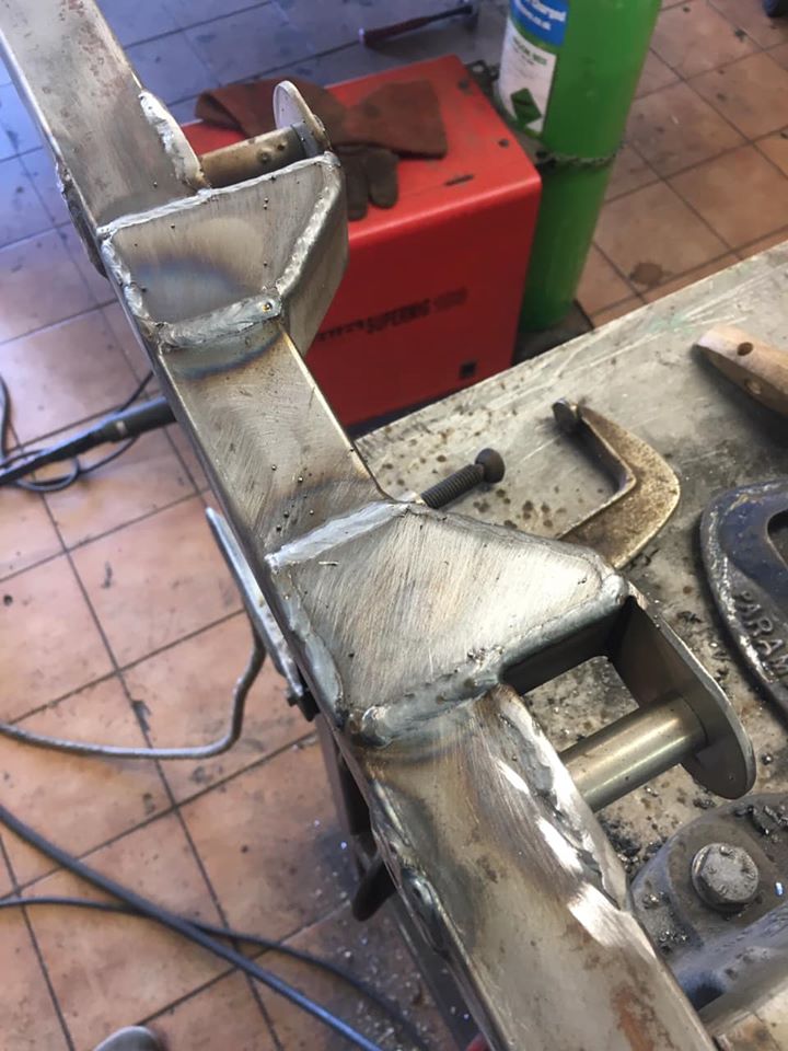
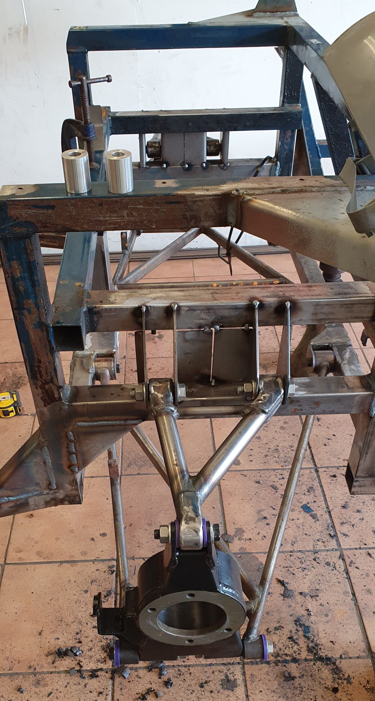
While it would have been easier to make a single mounting structure as we have done on the rear cross-member, there needed to be clearance for the front of the differential. That will make maintenance a little easier if the diff ever has to be removed.
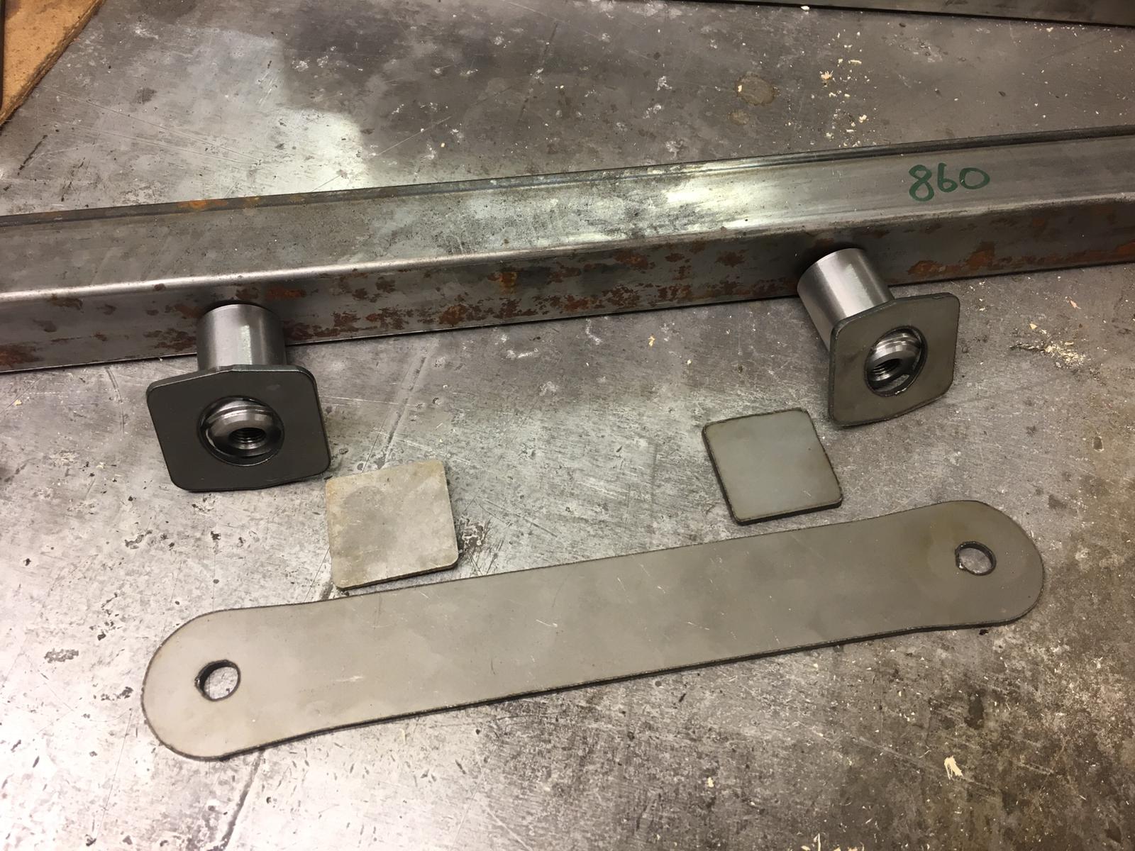
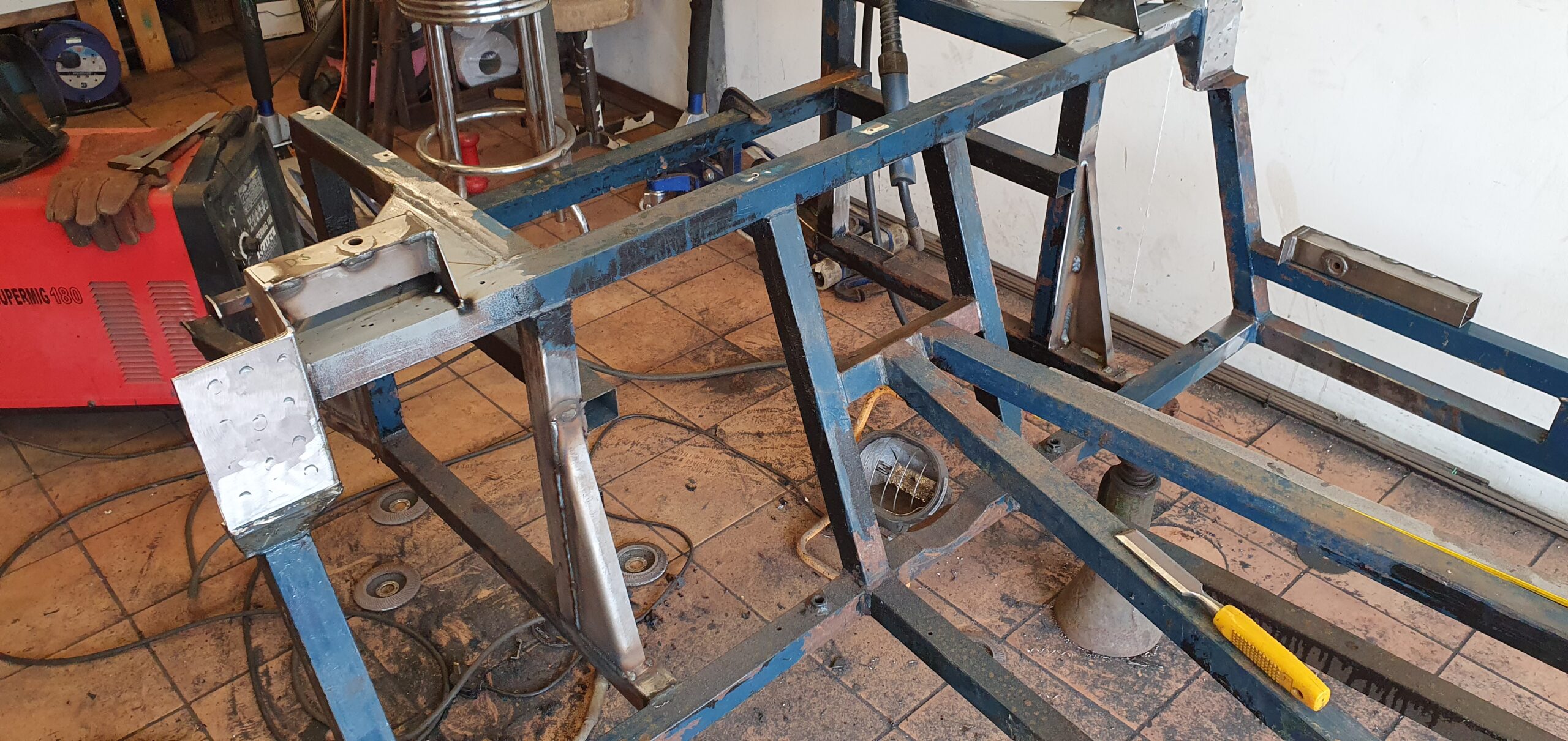
The suspension bolts will screw into the steel tubes which are welded through the chassis tube.
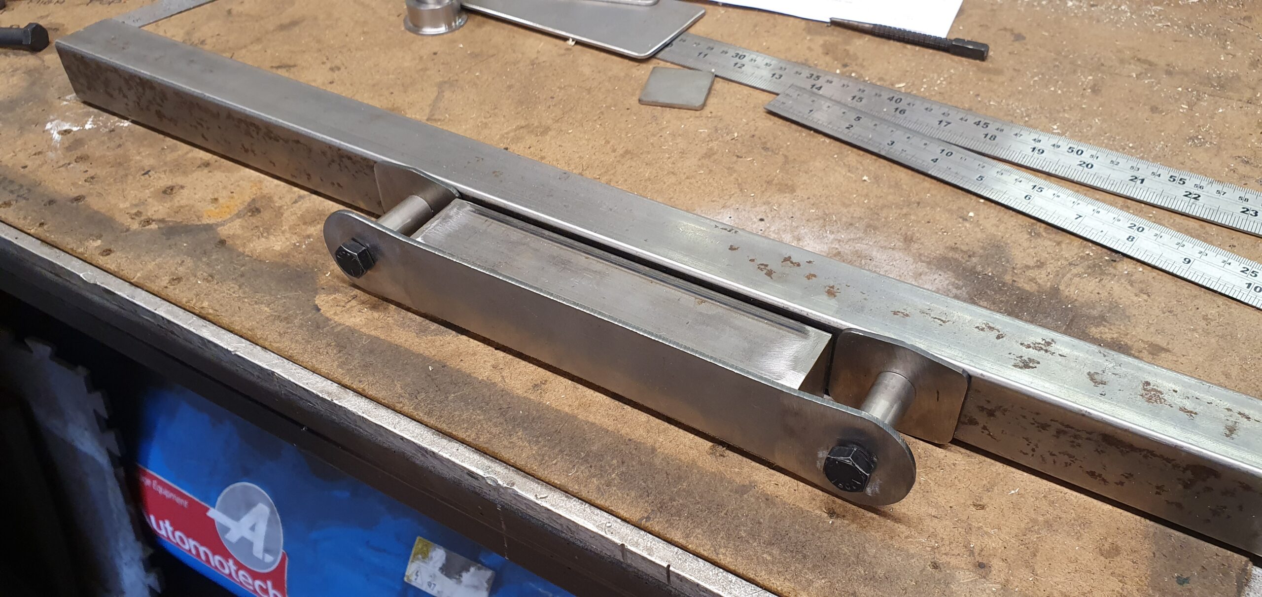
The plates on the chassis are slightly larger than the tube to protect the poly-bushes. Large fish-plates are to be fitted top and bottom to spread the load from the triangulation tubes and top-rear diff mount.
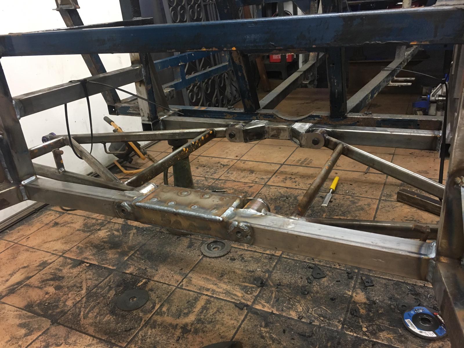
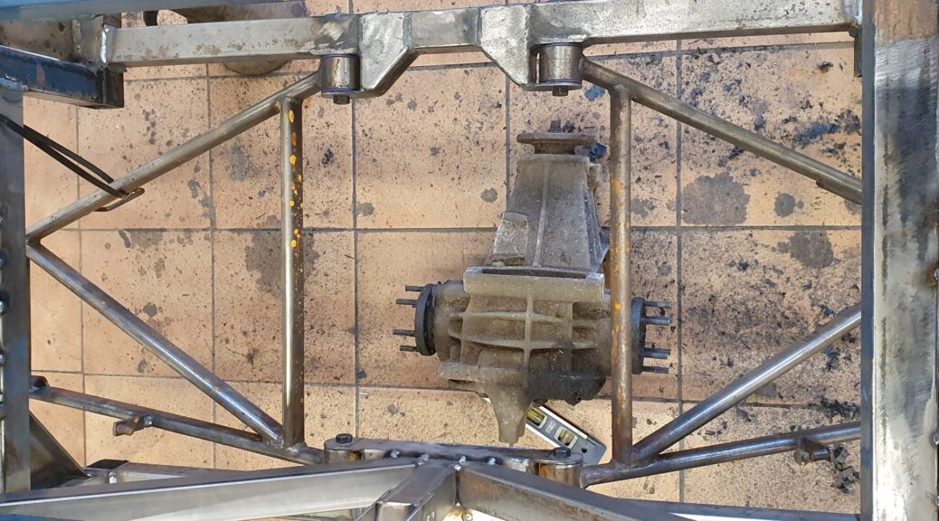
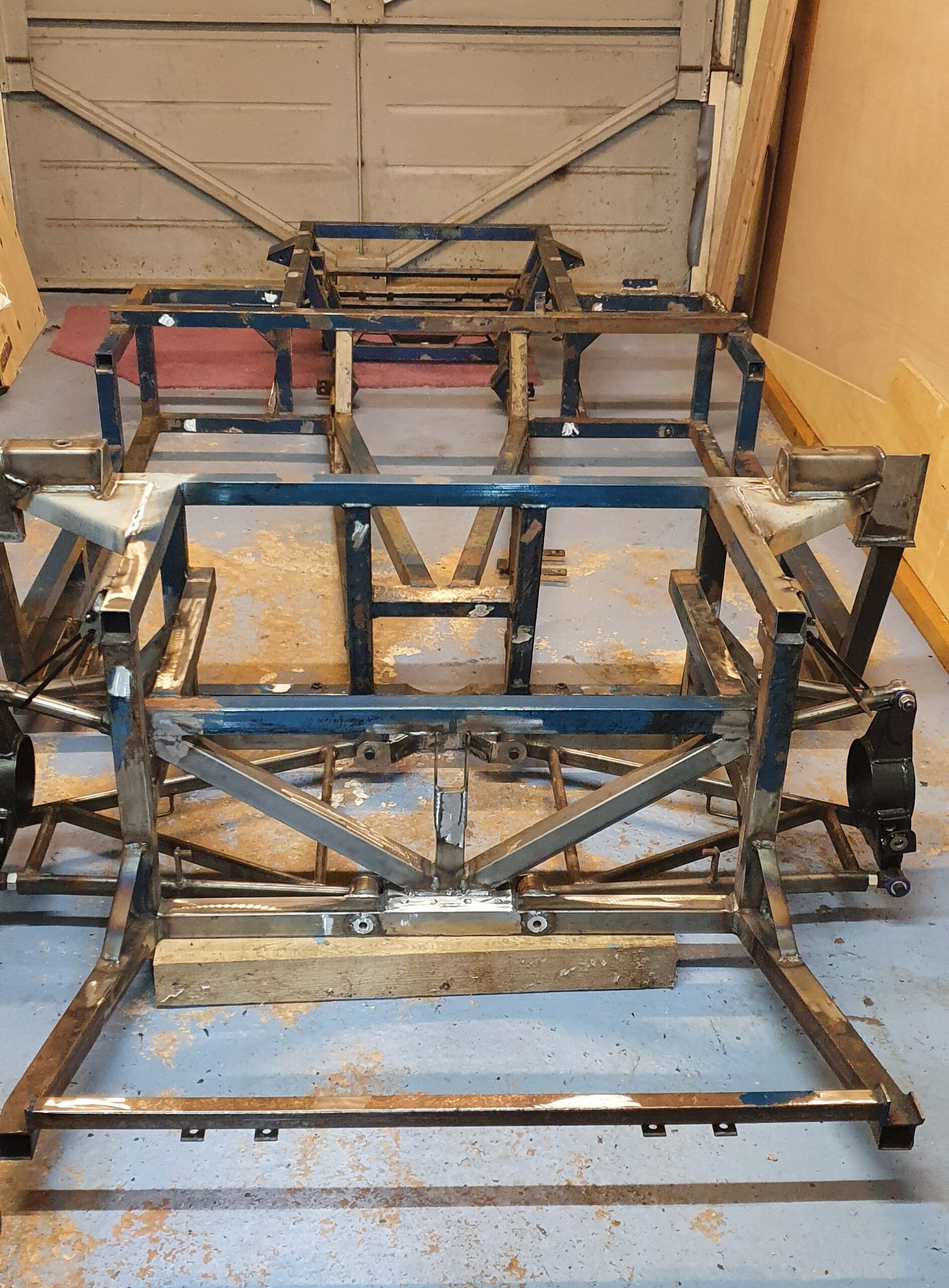
The rear cross-member position is easy to locate correctly and was used as the datum for all IRS components. First attach the rear cross-member then install the lower wishbones and tack the front cross-member where it needs to be. That ensures no strain on the wishbones.
From there the uprights are attached and the top wishbone position gives the exact location for the top wishbone mounts.
Its very satisfying that the geometry worked out perfectly.
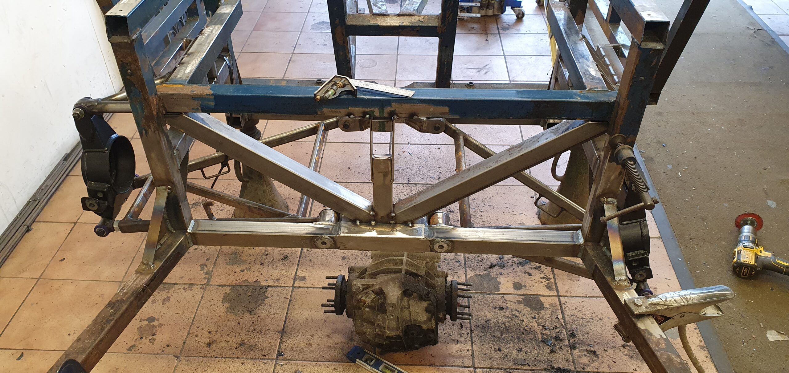
Triangulation tubes added along with the rear diff mount pick-up. The rear diff mount will not follow the standard Marcos design “P” bracket because that orients the poly bushes incorrectly. In fact all of the standard Marcos diff mounting is wrong in my opinion. Watch for an alternative design in a future instalment…

The last part of this stage of the build is the final weld-up. Yes there’s more to do but the next part of the design needs some real mock-up work to ensure the new diff mountings and additional cross-bracing work together and are still maintainable. I could do that in CAD of course, but I would have to accurately draw the diff and I honestly can’t be bothered!
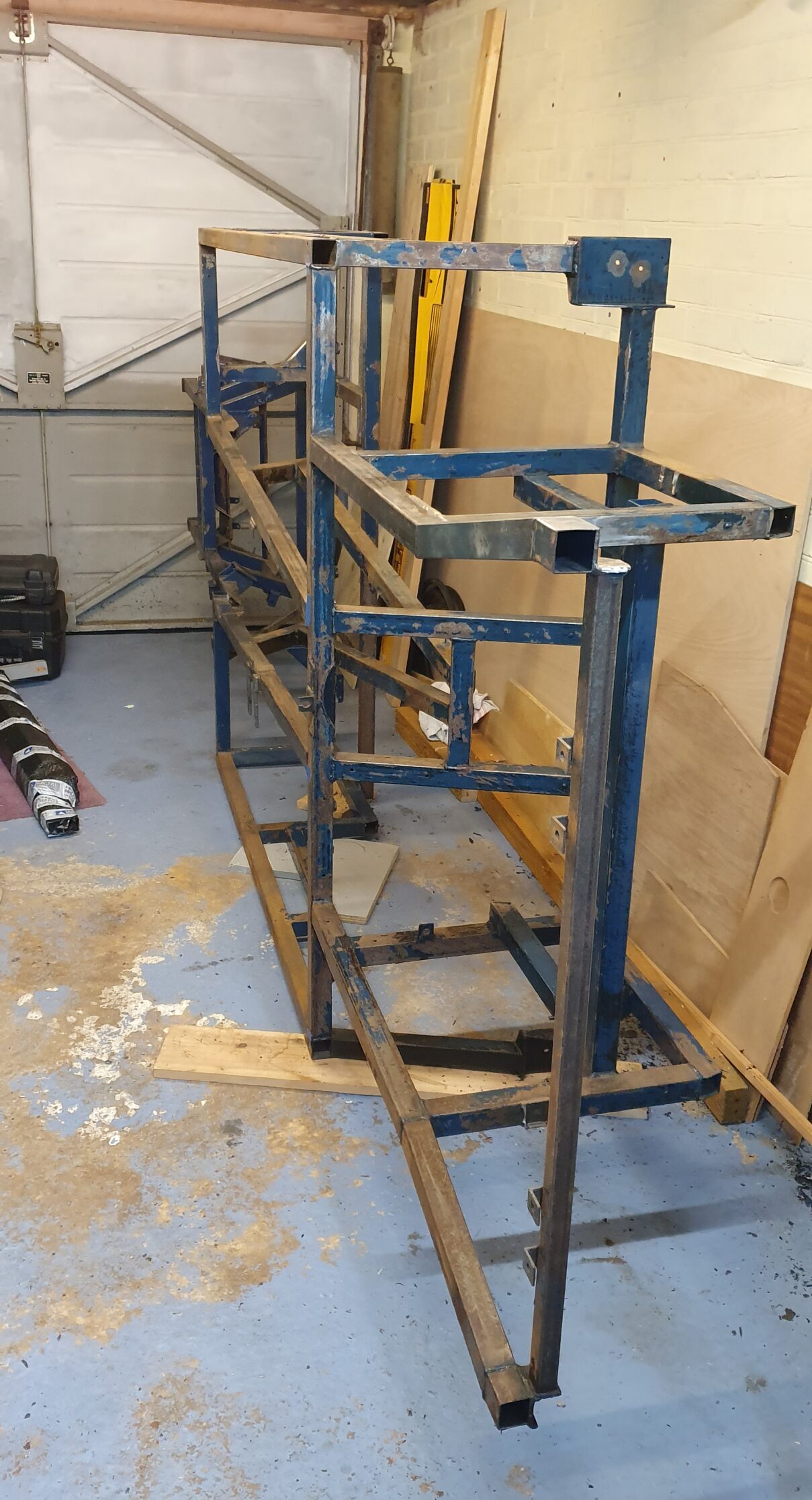
Here it is taking up a lot of valuable space! Unfortunately around this time despite the start of lock-down I had to start a complex contract and didn’t get a chance to get to grips with the diff mount mock-up. However I should be back on it in a few days and I can’t wait.
More in the next instalment.
Ian